MAX-7 / NEO-7 - Hardware Integration Manual
UBX-13003704 - R09 Production Information Design
Page 31 of 52
3.4.5 Design with GLONASS / GPS passive antenna
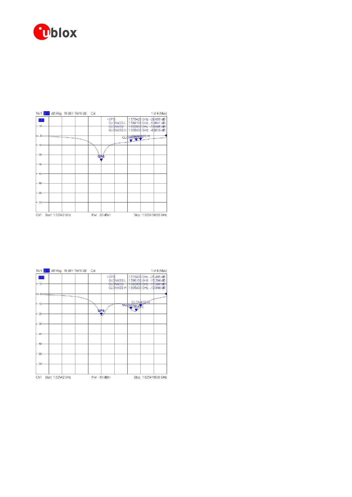
In general, GPS patch antennas only receive GPS signals well. A typical return plot (S11 measurement) shows
that the GLONASS signal is highly attenuated. (See Figure 28)
u-blox 7 modules supporting GLONASS have a GPS & GLONASS SAW filter that lets both GPS and GLONASS
signals pass. For best performance with passive antenna designs, use an external LNA. (See section 3.4.1.2).
Figure 28: 25*25*4 mm GPS patch antenna on 70*70 mm GND plane
To receive GPS and GLONASS, a special antenna patch (which can receive both GPS and GLONASS) is needed.
The return plot (S11 measurement) in Figure 29 below shows the two areas of lower attenuation.
Figure 29: 25*25*4 mm GPS / GLONASS patch antenna on 70*70 mm GND plane

 Loading...


