MAX-7 / NEO-7 - Hardware Integration Manual
UBX-13003704 - R09 Production Information Hardware description
Page 11 of 52
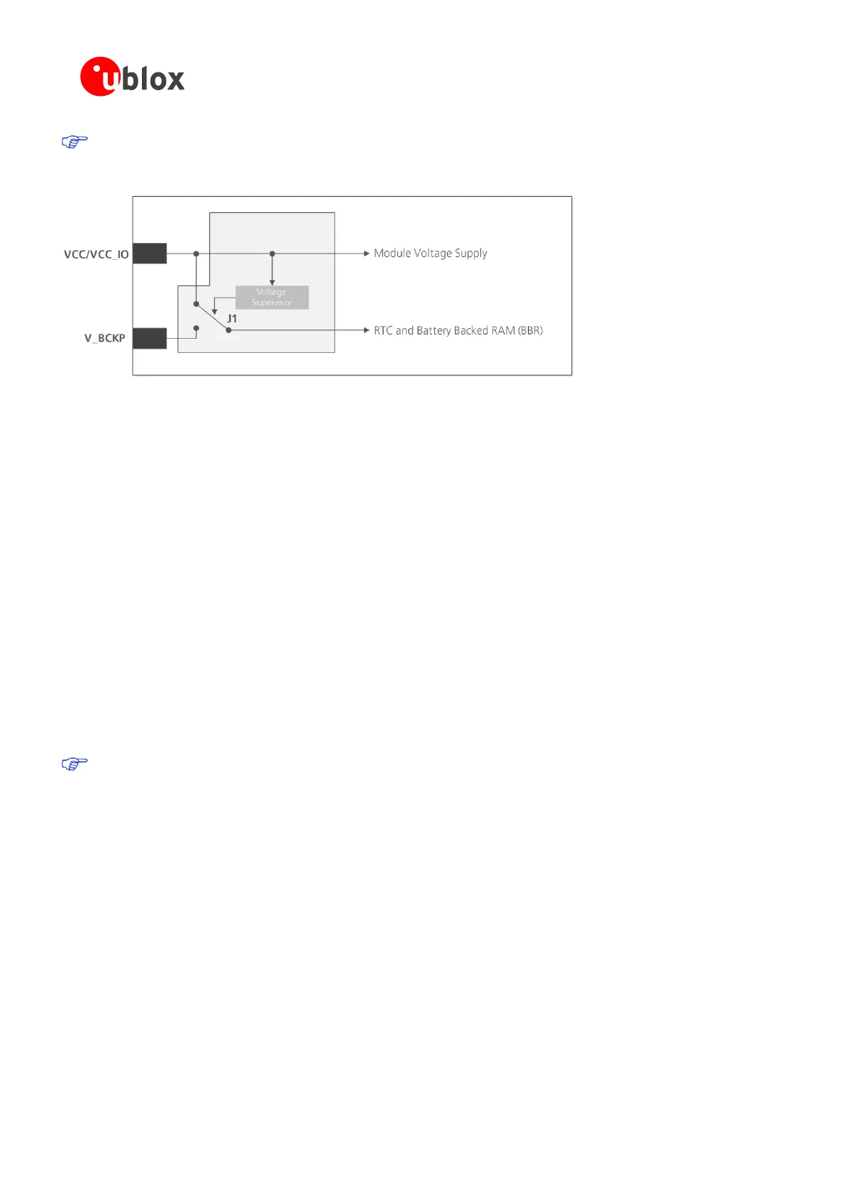
As long as the u-blox 7 module is supplied to VCC and VCC_IO, the backup battery is disconnected from
the RTC and the BBR to avoid unnecessary battery drain (see Figure 2). In this case, VCC supplies power to
the RTC and BBR.
Figure 2: Backup battery and voltage (for exact pin orientation, see data sheet)
2.5.3.1 RTC derived from the system clock; “Single Crystal” feature (MAX-7C)
On MAX-7C, the reference frequency for the RTC clock can be internally derived from the crystal system clock
frequency (26 MHz) when in Hardware Backup Mode. This feature is called “single crystal” operation. The
backup battery supplies the crystal via V_BCKP in the event that VDD_IO fails to provide power to derive and
maintain the RTC clock. This makes MAX-7C a more cost efficient solution, at the expense of a higher backup
current, compared to the usage of an ordinary RTC crystal on other MAX-7 variants. The capacity of the backup
battery at V_BCKP must be increased accordingly if Hardware Backup Mode is needed.
2.5.4 VDD_USB: USB interface power supply (NEO-7)
VDD_USB supplies the USB interface. If the USB interface is not used, the VDD_USB pin must be connected to
GND. For more information about correctly handling the VDD_USB pin, see section 2.6.2.1.
2.5.5 VCC_RF: Output voltage RF section
The VCC_RF pin can supply an active antenna or external LNA. For more information, see section 3.4.3.2.
2.5.6 V_ANT: Antenna supply (MAX-7W)
The V_ANT pin is available to provide antenna bias voltage to supply an optional external active antenna. For
more information, see section 3.4.3.2.
If not used, connect the V_ANT pin to GND.
2.6 Interfaces
2.6.1 UART
u-blox 7 positioning modules include a Universal Asynchronous Receiver Transmitter (UART) serial interface
RxD/TxD supporting configurable baud rates. The baud rates supported are specified in the u-blox 7 Receiver
Description Including Protocol Specification [4]
The signal output and input levels are 0 V to VCC for NEO-7 and 0 V to VCC_IO for MAX-7 modules. An
interface based on RS232 standard levels (+/- 12 V) can be implemented using level shifters such as Maxim
MAX3232. Hardware handshake signals and synchronous operation are not supported.
2.6.2 USB
A USB version 2.0 FS (Full Speed, 12 Mb/s) compatible interface is available for communication as an alternative
to the UART. The USB_DP integrates a pull-up resistor to signal a full-speed device to the host. The VDD_USB
pin supplies the USB interface.

 Loading...


