MAX-7 / NEO-7 - Hardware Integration Manual
UBX-13003704 - R09 Production Information Design
Page 17 of 52
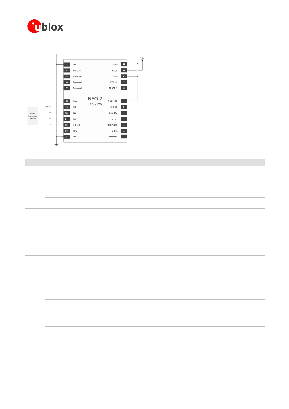
3.2.1 Minimal design (NEO-7N)
Figure 5: NEO-7 passive antenna design
Provide clean and stable supply.
Assure a good GND connection to all GND pins of the module,
preferably with a large ground plane.
It is recommended to connect a backup supply voltage to V_BCKP
in order to enable Warm and Hot Start features on the positioning
modules. Otherwise, connect to VCC.
To use the USB interface connect this pin to 3.0 – 3.6 V.
If no USB serial port used connect to GND.
GPS signal input
from antenna
The connection to the antenna has to be routed on the PCB. Use a
controlled impedance of 50 to connect RF_IN to the antenna or
the antenna connector. DC block inside.
Output voltage
RF section
VCC_RF can be used to power an external active antenna.
Communication interface, Can be programmed as TX Ready for
DDC interface. If pin 2 low => SPI MISO.
Serial input. Internal pull-up resistor to VCC. Leave open if
not used. If pin 2 low => SPI MOSI.
USB bidirectional communication pin. Leave open if unused.
Implementations see section 2.6.2.
Configurable time pulse signal (one pulse per second by default).
Leave open if not used.
External Interrupt pin.
Internal pull-up resistor to VCC. Leave open if not used.
DDC Data
If pin 2 low => SPI chip select.
DDC Clock. If pin 2 low => SPI clock.
ANT_ON (NEO-7N)
RESERVED (NEO-7M)
ANT_ON (antenna on) HIGH can be used to turn on and LOW to
turn off an optional external LNA.
Used to select UART/DDC or SPI
Open = UART/DDC; low = SPI
Table 4: Pinout NEO-7

 Loading...


