MAX-7 / NEO-7 - Hardware Integration Manual
UBX-13003704 - R09 Production Information Design
Page 24 of 52
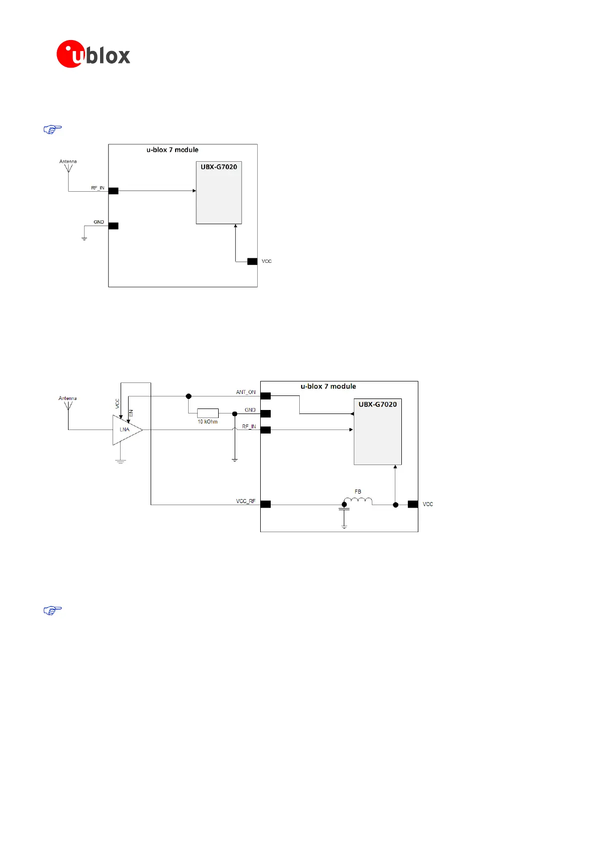
3.4.1.1 Minimal setup with a good patch antenna
Figure 17 shows a minimal setup for a design with a good GPS patch antenna.
NEO-7N is optimized for immunity to near field cellular signals.
Figure 17: Module design with passive antenna
3.4.1.2 Setup for best performance with passive antenna
Figure 18 shows a design using an external LNA to increase the sensitivity for best performance with passive
antenna.
Figure 18: Module design with passive antenna and external LNA
ANT_ON (antenna on) can be used to turn on and off an optional external LNA.
The VCC_RF output can be used to supply the LNA with a filtered supply voltage.
A standard GPS LNA has enough bandwidth to amplify GPS and GLONASS signals.
3.4.2 Active antenna design without antenna supervisor (NEO-7N/7M/7P, MAX-7C/7Q)
Active antennas have an integrated low-noise amplifier. Active antennas require a power supply that will
contribute to the total GPS system power consumption budget with additional 5 to 20 mA typically.
If the supply voltage of the u-blox 7 receiver matches the supply voltage of the antenna (e.g. 3.0 V), use the
filtered supply voltage VCC_RF output to supply the antenna. See section 3.4.2.1. This design is used for
modules MAX-7C, MAX-7Q, NEO-7N, and NEO-7M in combination with active antenna.
In case of different supply voltage, use a filtered external supply as shown in section 3.4.2.2

 Loading...


