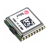
MAX-7 / NEO-7 - Hardware Integration Manual
UBX-13003704 - R09 Production Information Migration to u-blox-7 modules
Page 37 of 52
6.2.3 Hardware migration MAX-6 -> MAX-7
If on u-blox 6 module this was connected to GND,
no problem to do the same in u-blox 7.
(MAX-7C: Higher backup current, see 2.5.3.1
Single Crystal)
IO supply voltage
Input must be
always supplied.
Usually connect to
VCC pin 8
IO supply voltage
Input must be
always supplied.
Usually connect to
VCC pin 8
Power supply of
module
MAX-6G 1.75 –
2.0V
MAX-6Q/C: 2.7 –
3.6V
Power supply of
module
MAX-7C: 1.65 –
3.6V
MAX-7Q: 2.7 –
3.6V
With MAX-6, if Reset input is used, it implements
the 3k3 resistor from pin 9 to pin 8. This also
works with MAX-7. If used with MAX-7, do not
populate the pull-up resistor.
Matched RF-Input,
DC block inside.
Matched RF-Input,
DC block inside.
Active antenna or
ext. LNA control
pin in power save
mode.
ANT_ON pin
voltage level: MAX-
6 -> VCC_RF (pull-
up)
Active antenna or
ext. LNA control
pin in power save
mode.
ANT_ON pin
voltage level: MAX-
7 -> VCC_IO (push-
pull)
On MAX-6, ANT_ON pin voltage level is with
respect to VCC_RF, on MAX-7 to VCC_IO
(only relevant when VCC_IO does not share the
same supply with VCC)
Can be used for
active antenna or
external LNA
supply.
Can be used for
active antenna or
external LNA
supply.
RESERVED
(MAX-7W:
V_ANT )
Table 14: Pin-out comparison MAX-6 vs. MAX-7

 Loading...