LEA-6 / NEO-6 / MAX-6 - Hardware Integration Manual
UBX-14054794 Production Information Product handling
Page 60 of 85
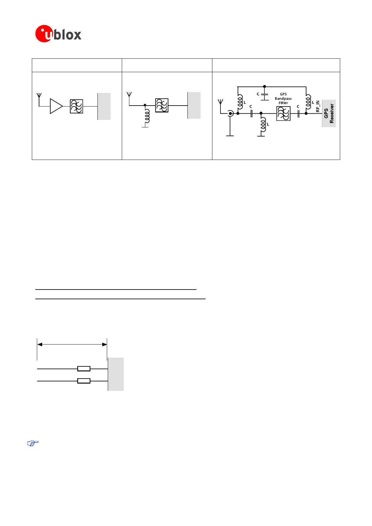
Small passive antennas (<2 dBic and
performance critical)
Passive antennas (>2 dBic or
performance sufficient)
Active Antennas (without internal filter which need
the module antenna supervisor circuits)
RF_IN
GPS
Receiver
LNA
GPS
Bandpass
Filtler
RF_IN
GPS
Receiver
L
GPS
Bandpass
Filtler
LNA with appropriate ESD rating and
maximum input power
GPS Bandpass Filter: SAW or Ceramic
with low insertion loss and appropriate
ESD rating
Figure 57: EOS and ESD Precautions
3.3.7 Electromagnetic interference (EMI)
Electromagnetic interference (EMI) is the addition or coupling of energy originating from any RF emitting device.
This can cause a spontaneous reset of the GPS receiver or result in unstable performance. Any unshielded line or
segment (>3mm) connected to the GPS receiver can effectively act as antenna and lead to EMI disturbances or
damage.
The following elements are critical regarding EMI:
Unshielded connectors (e.g. pin rows etc.)
Weakly shielded lines on PCB (e.g. on top or bottom layer and especially at the border of a PCB)
Weak GND concept (e.g. small and/or long ground line connections)
EMI protection measures are recommended when RF emitting devices are near the GPS receiver. To minimize the
effect of EMI a robust grounding concept is essential. To achieve electromagnetic robustness follow the standard
EMI suppression techniques.
http://www.murata.com/products/emc/knowhow/index.html
http://www.murata.com/products/emc/knowhow/pdf/4to5e.pdf
Improved EMI protection can be achieved by inserting a resistor (e.g. R>20 ) or better yet a ferrite bead
(BLM15HD102SN1) or an inductor (LQG15HS47NJ02) into any unshielded PCB lines connected to the GPS
receiver. Place the resistor as close as possible to the GPS receiver pin.
Example of EMI protection measures on the RX/TX line using a ferrite bead:
TX
RX
GPS
Receiver
FB
FB
BLM15HD102SN1
>10mm
Figure 58: EMI Precautions
VCC can be protected using a feed thru capacitor. For electromagnetic compatibility (EMC) of the RF_IN pin refer
to section 3.3.6
Intended use
In order to mitigate any performance degradation of a radio equipment under EMC disturbance, system
integration shall adopt appropriate EMC design practice and not contain cables over three meters on
signal and supply ports.

 Loading...


