LEA-6 / NEO-6 / MAX-6 - Hardware Integration Manual
UBX-14054794 Production Information Hardware description
Page 8 of 85
1.3 Power management
1.3.1 Connecting power
u-blox 6 receiver modules have three power supply pins: VCC, V_BCKP and VDDUSB.
(No VDDUSB for MAX-6)
1.3.1.1 VCC - main power
The main power supply is fed through the VCC pin. During operation, the current drawn by the u-blox 6 GPS
module can vary by some orders of magnitude, especially, if low-power operation modes are enabled. It is
important that the system power supply circuitry is able to support the peak power (see data sheet for
specification) for a short time. In order to define a battery capacity for specific applications the sustained power
figure shall be used.
When switching from backup mode to normal operation or at start-up u-blox 6 modules must charge the
internal capacitors in the core domain. In certain situations this can result in a significant current draw. For
low power applications using Power Save and backup modes it is important that the power supply or low
ESR capacitors at the module input can deliver this current/charge.
1.3.1.2 V_BCKP - backup battery
In case of a power failure on pin VCC, the real-time clock and backup RAM are supplied through pin V_BCKP.
This enables the u-blox 6 receiver to recover from a power failure with either a Hotstart or a Warmstart
(depending on the duration of VCC outage) and to maintain the configuration settings saved in the backup
RAM. If no backup battery is connected, the receiver performs a Coldstart at power up.
If no backup battery is available connect the V_BCKP pin to GND.
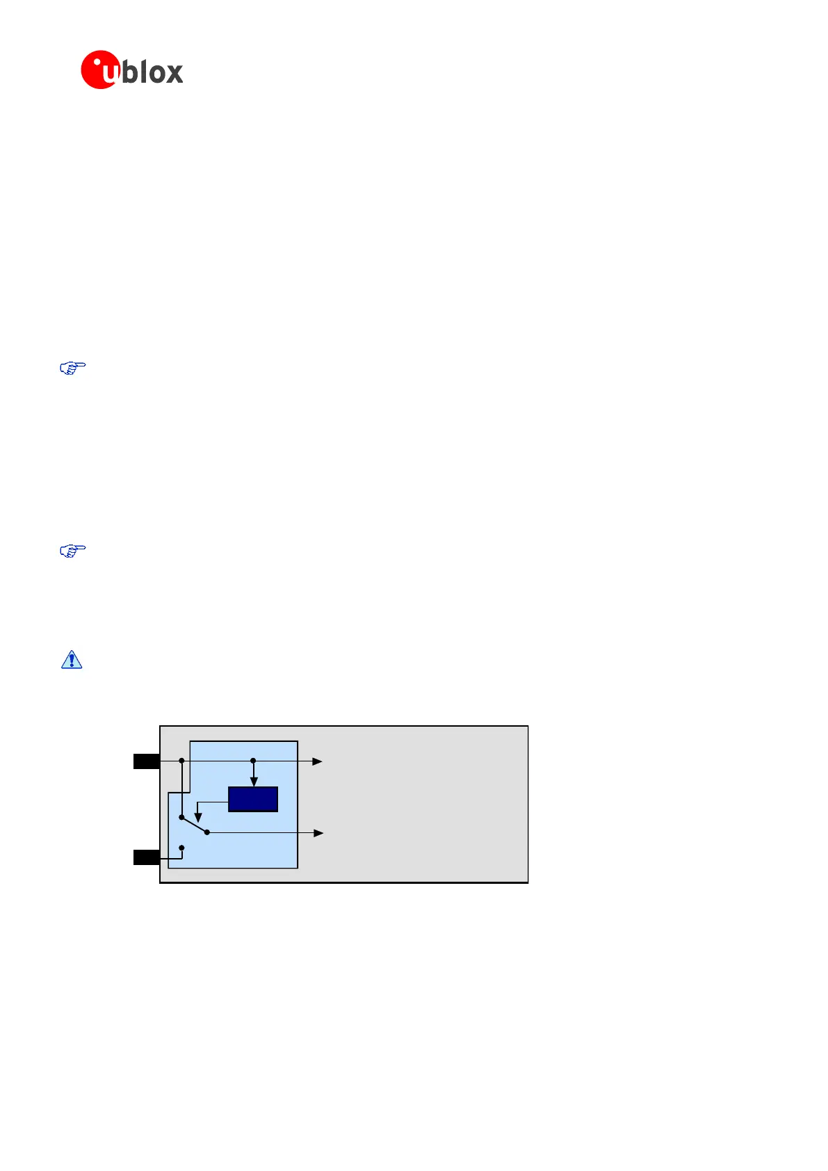
As long as VCC is supplied to the u-blox 6 receiver, the backup battery is disconnected from the RTC and the
backup RAM in order to avoid unnecessary battery drain (see Figure 2). Power to RTC and BBR is supplied from
VCC in this case.
Avoid high resistance on the on the V_BCKP line: During the switch from main supply to backup
supply a short current adjustment peak can cause high voltage drop on the pin and possible
malfunctions.
VCC
V_BCKP
Voltage
Supervisor
Module Voltage Supply
RTC and Battery Backup RAM (BBR)
J1
Figure 2: Backup Battery and Voltage
1.3.1.3 VDD_USB - USB interface power supply
On LEA-6 and NEO-6 VDD_USB supplies the USB interface. If the USB interface is not used, the VDD_USB pin
must be connected to GND. For more information regarding the correct handling of VDD_USB, see section
1.6.2.1.

 Loading...


