SARA-G3 and SARA-U2 series - System Integration Manual
UBX-13000995 - R26 Design-in
Page 115 of 217
2.3 System functions interfaces
2.3.1 Module power-on (PWR_ON)
2.3.1.1 Guidelines for PWR_ON circuit design
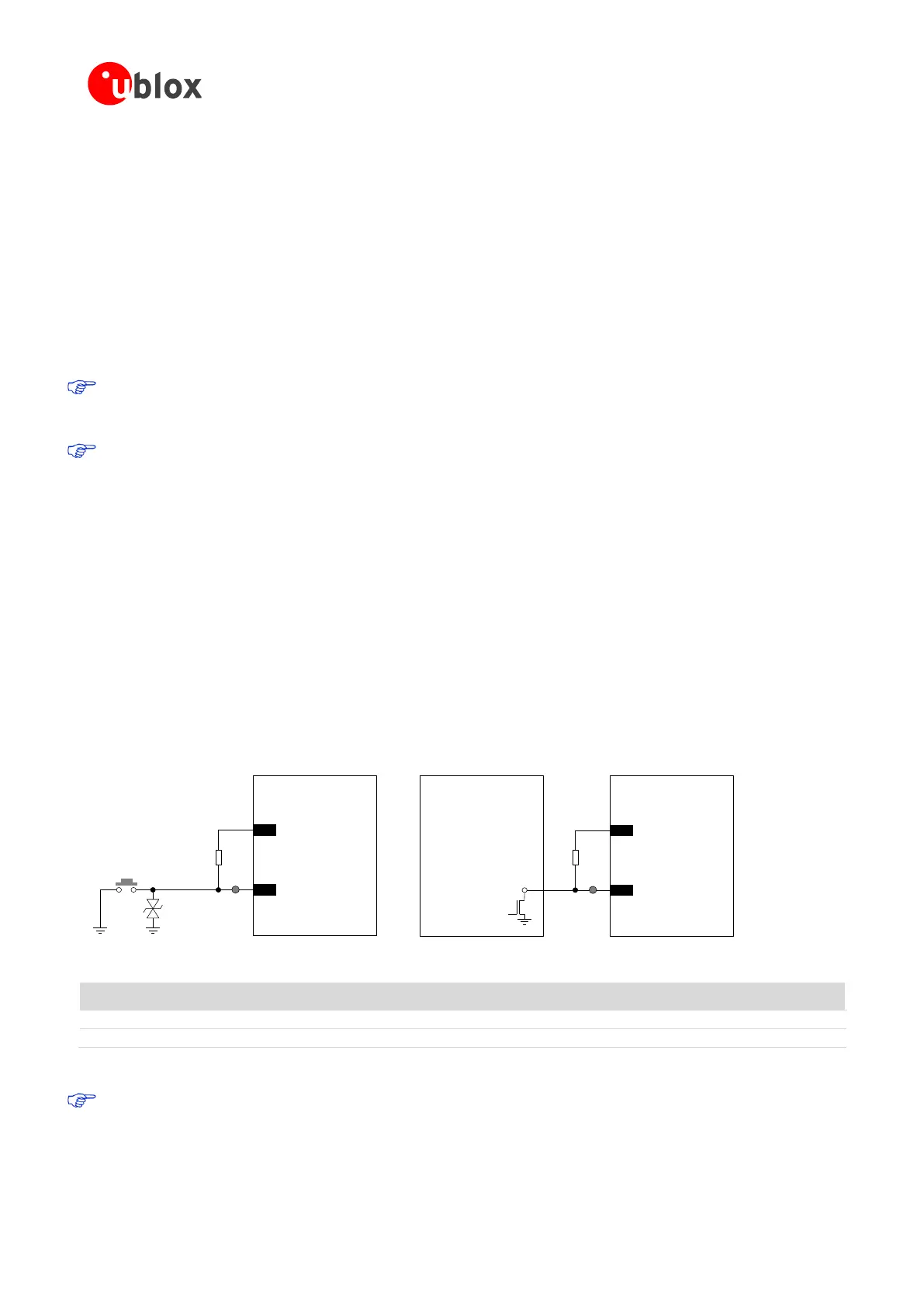
Connecting the PWR_ON input to a push button that shorts the PWR_ON pin to ground, provide an external
pull-up resistor (e.g. 100 kΩ) biased by the V_BCKP supply pin of the module, as described in Figure 52 and
Table 33. Connecting the PWR_ON input to a push button, the pin will be externally accessible on the
application device: according to EMC/ESD requirements of the application, provide an additional ESD protection
(e.g. EPCOS CA05P4S14THSG varistor array) on the line connected to this pin, close to accessible point.
The PWR_ON pin has high input impedance and is weakly pulled to the high level on the module. Avoid
keeping it floating in a noisy environment. To hold the high logic level stable, the PWR_ON pin must be
connected to a pull-up resistor (e.g. 100 kΩ) biased by the V_BCKP supply pin of the module.
The ESD sensitivity rating of the PWR_ON pin is 1 kV (Human Body Model according to JESD22-A114). A
higher protection level can be required if the line is externally accessible on the application board, e.g. if
an accessible push button is directly connected to PWR_ON pin. A higher protection level can be achieved
by mounting an ESD protection (e.g. EPCOS CA05P4S14THSG varistor array) close to accessible points.
When connecting the PWR_ON input to an external device (e.g. application processor), use an open drain
output on the external device with an external pull-up resistor (e.g. 100 kΩ) biased by the V_BCKP supply pin of
the module, as described in Figure 52 and Table 33.
A compatible push-pull output of an application processor can also be used: in this case the pull-up can be
provided to pull the PWR_ON level high when the application processor is switched off. If the high-level voltage
of the push-pull output pin of the application processor is greater than the maximum input voltage operating
range of the V_BCKP pin (refer to the SARA-G3 series Data Sheet [1] and the SARA-U2 series Data Sheet [2]),
the V_BCKP supply cannot be used to bias the pull-up resistor: the supply rail of the application processor or the
module VCC supply could be used, but this increases the V_BCKP (RTC supply) current consumption when the
module is in not-powered mode (VCC supply not present). Using a push-pull output of the external device, take
care to fix the proper level in all the possible scenarios to avoid an inappropriate module switch-on.
SARA-G3 series
SARA-U2 series
Rext
2
V_BCKP
15
PWR_ON
Power-on
push button
ESD
Open
Drain
Output
Application
Processor
SARA-G3 series
SARA-U2 series
Rext
2
V_BCKP
15
PWR_ON
TP
TP
Figure 52: PWR_ON application circuits using a push button and an open drain output of an application processor
100 kΩ Resistor 0402 5% 0.1 W
External pull-up resistor
Varistor array for ESD protection
Table 33: Example of pull-up resistor and ESD protection for the PWR_ON application circuit
It is recommended to provide direct access to the PWR_ON pin on the application board by means of an
accessible test-point directly connected to the PWR_ON pin.
 Loading...


