SARA-G3 and SARA-U2 series - System Integration Manual
UBX-13000995 - R26 Design-in
Page 171 of 217
2.15 Schematic for SARA-G3 and SARA-U2 series module integration
2.15.1 Schematic for SARA-G300 / SARA-G310 modules integration
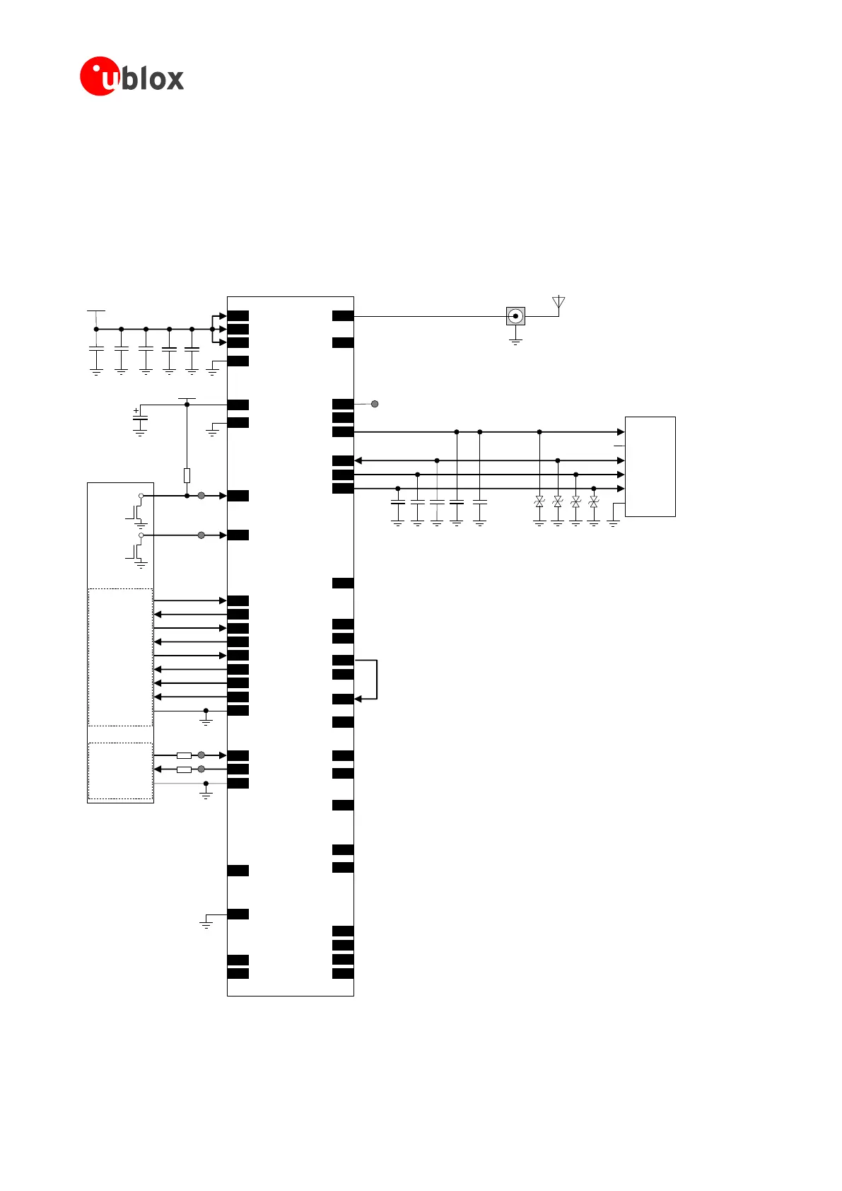
Figure 91 is an example of a schematic diagram where a SARA-G300 / SARA-G310 module is integrated into an
application board, using all the available interfaces and functions of the module.
TXD
RXD
RTS
CTS
DTR
DSR
RI
DCD
GND
12
TXD
9 DTR
13
RXD
10
RTS
11
CTS
6 DSR
7 RI
8 DCD
GND
3V8
GND
330µF
10nF100nF 56pF
SARA-G300/SARA-G310
52 VCC
53 VCC
51 VCC
+
100µF
2 V_BCKP
GND
GND
GND
RTC
back-up
1.8V DTE
1.8V DTE
16
RSVD
18 RESET_N
Application
Processor
Open
Drain
Output
15 PWR_ON
100kΩ
Open
Drain
Output
TXD
RXD
29
TXD_AUX
28
RXD_AUX
0Ω
0Ω
TP
TP
RSVD
RSVD
32K_OUT
RSVD
26
27
24
25
RSVD
23
RSVD
RSVD
RSVD
RSVD
37
36
35
34
44RSVD
45RSVD
49RSVD
48RSVD
46RSVD
47RSVD
15pF
33
RSVD
17
RSVD
19
RSVD
47pF
SIM Card Holder
CCVCC (C1)
CCVPP (C6)
CCIO (C7)
CCCLK (C3)
CCRST (C2)
GND (C5)
47pF 47pF 100nF
41VSIM
39SIM_IO
38SIM_CLK
40SIM_RST
47pF
4V_INT
42SIM_DET
ESD ESD ESD ESD
56ANT
62RSVD
Connector External
Antenna
V_BCKP
TP
TP
TP
EXT32K 31
Figure 91: Example of schematic diagram to integrate SARA-G300/G310 modules in an application board, using all the interfaces
 Loading...


