SARA-G3 and SARA-U2 series - System Integration Manual
UBX-13000995 - R26 Appendix
Page 208 of 217
B Migration between SARA-G3 and SARA-U2
B.1 Overview
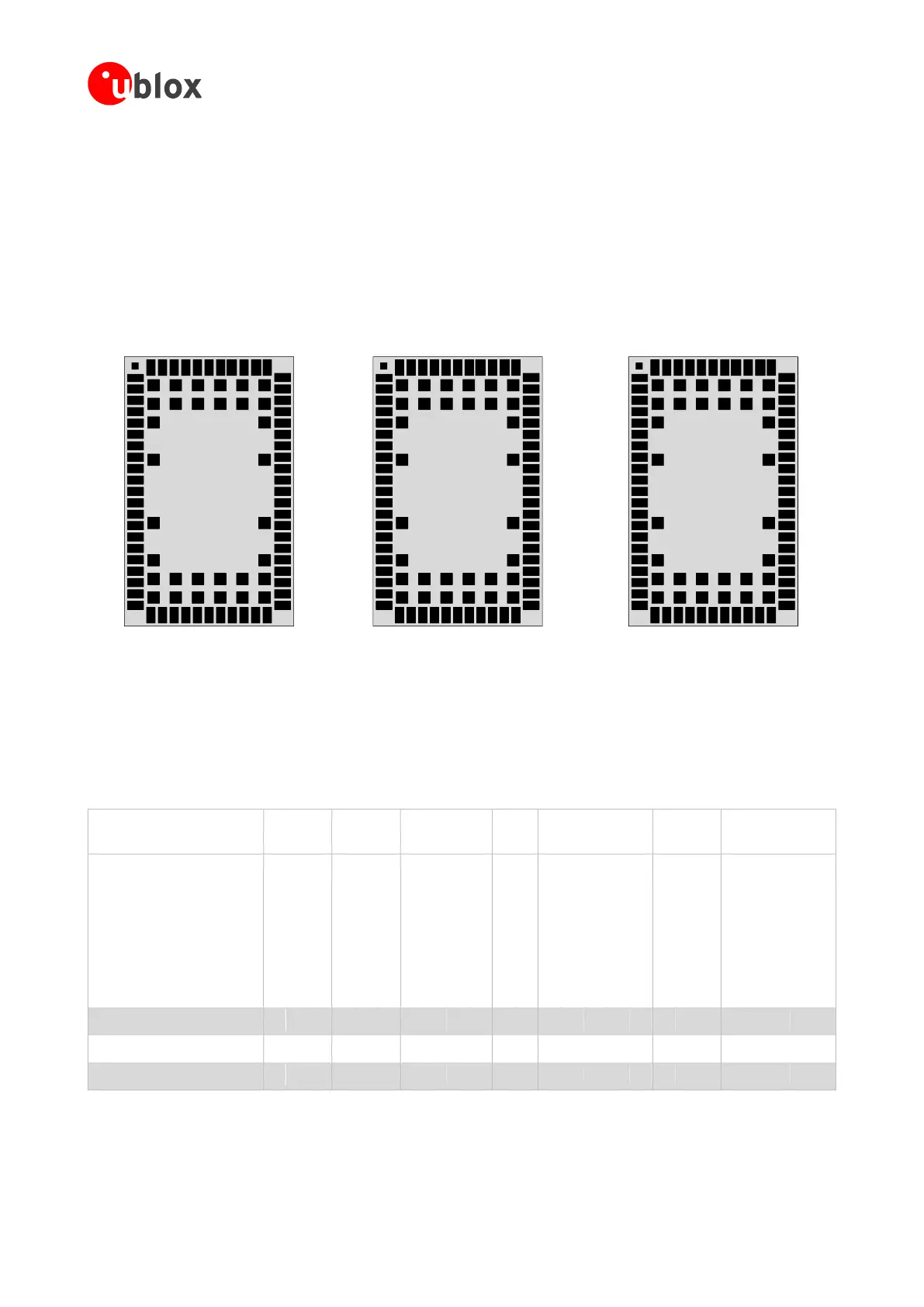
SARA-G3 and SARA-U2 series cellular modules have exactly the same SARA form factor (26.0 x 16.0 mm LGA)
with exactly the same 96-pin layout as described in Figure 97, so that the modules can be alternatively mounted
on a single application board using exactly the same copper mask, solder mask and paste mask.
64 63 61 60 58 57 55 54
22 23 25 26 28 29 31 32
11
10
8
7
5
4
2
1
21
19
18
16
15
13
12
43
44
46
47
49
50
52
53
33
35
36
38
39
41
42
65 66 67 68 69 70
71 72 73 74 75 76
77 78
79 80
81 82
83 84
85 86 87 88 89 90
91 92 93 94 95 96
CTS
RTS
DCD
RI
V_INT
V_BCKP
GND
RSVD
RESET_N
RSVD
PWR_ON
RXD
TXD
3
20
17
14
9
6
24 27 30
51
48
45
40
37
34
5962 56
GND
GND
DSR
DTR
GND
RSVD
GND
GND
RXD_AUX
TXD_AUX
EXT32K
GND
RSVD
32K_OUT
RSVD
RSVD
RSVD
GND
GND
GND
RSVD
RSVD
RSVD
RSVD
GND
VCC
VCC
RSVD
RSVD
RSVD
SIM_CLK
SIM_IO
VSIM
SIM_DET
VCC
RSVD
RSVD
SIM_RST
RSVD
RSVD
GND
GND
GND
GND
GND
GND
GND
GND
GND
RSVD
ANT
SARA-G300
SARA-G310
Top View
Pin 65-96: GND
64 63 61 60 58 57 55 54
22 23 25 26 28 29 31 32
11
10
8
7
5
4
2
1
21
19
18
16
15
13
12
43
44
46
47
49
50
52
53
33
35
36
38
39
41
42
65 66 67 68 69 70
71 72 73 74 75 76
77 78
79 80
81 82
83 84
85 86 87 88 89 90
91 92 93 94 95 96
CTS
RTS
DCD
RI
V_INT
V_BCKP
GND
RSVD
RESET_N
GPIO1
PWR_ON
RXD
TXD
3
20
17
14
9
6
24 27 30
51
48
45
40
37
34
5962 56
GND
GND
DSR
DTR
GND
RSVD
GND
GND
RXD_AUX
TXD_AUX
RSVD
GND
GPIO2
GPIO3
SDA
SCL
GPIO4
GND
GND
GND
SPK_P
MIC_BIAS
MIC_GND
MIC_P
GND
VCC
VCC
RSVD
I2S_TXD
I2S_CLK
SIM_CLK
SIM_IO
VSIM
SIM_DET
VCC
MIC_N
SPK_N
SIM_RST
I2S_RXD
I2S_WA
GND
GND
GND
GND
GND
GND
GND
GND
GND
ANT_DET
ANT
SARA-G340
SARA-G350
Top View
Pin 65-96: GND
64 63 61 60 58 57 55 54
22 23 25 26 28 29 31 32
11
10
8
7
5
4
2
1
21
19
18
16
15
13
12
43
44
46
47
49
50
52
53
33
35
36
38
39
41
42
65 66 67 68 69 70
71 72 73 74 75 76
77 78
79 80
81 82
83 84
85 86 87 88 89 90
91 92 93 94 95 96
CTS
RTS
DCD
RI
V_INT
V_BCKP
GND
CODEC_CLK
RESET_N
GPIO1
PWR_ON
RXD
TXD
3
20
17
14
9
6
24 27 30
51
48
45
40
37
34
5962 56
GND
GND
DSR
DTR
GND
VUSB_DET
GND
GND
USB_D-
USB_D+
RSVD
GND
GPIO2
GPIO3
SDA
SCL
GPIO4
GND
GND
GND
RSVD
RSVD
RSVD
RSVD
GND
VCC
VCC
RSVD
I2S_TXD
I2S_CLK
SIM_CLK
SIM_IO
VSIM
SIM_DET
VCC
RSVD
RSVD
SIM_RST
I2S_RXD
I2S_WA
GND
GND
GND
GND
GND
GND
GND
GND
GND
ANT_DET
ANT
SARA-U2
Top View
Pin 65-96: GND
Figure 100: SARA-G3 and SARA-U2 series modules pin layout and pin assignment
Table 69 summarizes the interfaces provided by SARA-G3 and SARA-U2 series modules: all the interfaces
provided by different modules are electrically compatible, so that the same compatible external circuit can be
implemented on the application board.
• = supported by all product versions
■ = supported by ‘04’ product versions onwards
Table 69: Summary of SARA-G3 and SARA-U2 series modules interfaces
 Loading...


