SARA-G3 and SARA-U2 series - System Integration Manual
UBX-13000995 - R26 Appendix
Page 211 of 217
B.3 Schematic for SARA-G3 and SARA-U2 integration
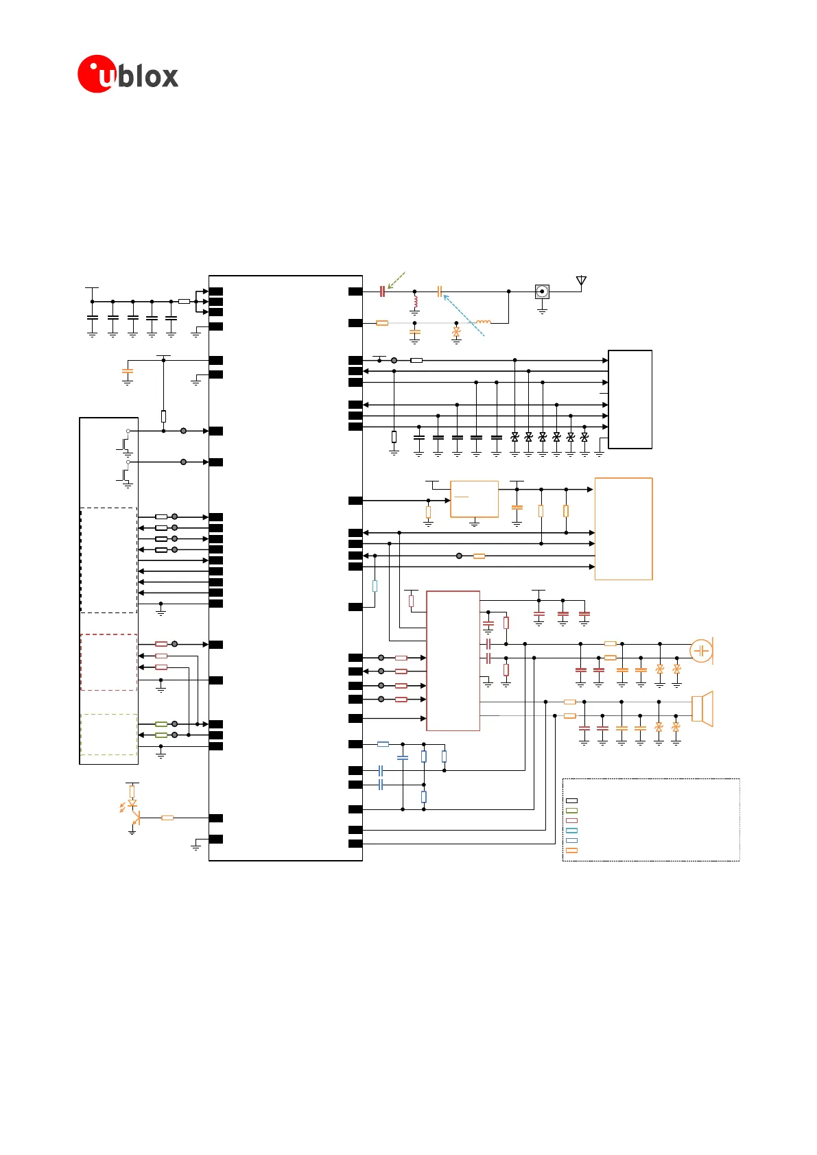
Figure 101 shows an example of a schematic diagram where a SARA-G3 or SARA-U2 series module can be
integrated into the same application board, using all the available interfaces and functions of the modules. The
different mounting options for the external parts are highlighted in different colors as described in the legend,
according to the interfaces supported by the relative modules.
TXD
RXD
RTS
CTS
DTR
DSR
RI
DCD
GND
12 TXD
9 DTR
13 RXD
10 RTS
11 CTS
6 DSR
7 RI
8 DCD
GND
3V8
GND
330µF
10nF100nF 56pF
SARA-G3 / SARA-U2
52 VCC
53 VCC
51 VCC
+
100µF
2 V_BCKP
GND GND
GND
RTC
back-up
1.8V UART DTE
1.8V UART DTE
16 RSVD / GPIO1
3V8
Network
Indicator
18 RESET_N
Application
Processor
Open
Drain
Output
15 PWR_ON
100k
Open
Drain
Output
TXD
RXD
29
TXD_AUX / USB_D+
28
RXD_AUX / USB_D-
0Ω
0Ω
TP
TP
15pF
33 RSVD
V_BCKP
TP
TP
47pF
SIM Card
Connector
CCVCC (C1)
CCVPP (C6)
CCIO (C7)
CCCLK (C3)
CCRST (C2)
GND (C5)
47pF 47pF 100nF
41VSIM
39SIM_IO
38SIM_CLK
40SIM_RST
47pF
SW1
SW2
4V_INT
42SIM_DET
470k
ESD ESD ESD ESD ESD ESD
56
ANT
62ANT_DET
10k 82nH
33pF
Connector
27pF
ESD
External
Antenna
1k
TP
u-blox 1.8V
GNSS Receiver
4.7k
OUTIN
GND
LDO Regulator
SHDN
RSVD / SDA
RSVD / SCL
4.7k
3V8 1V8_GPS
SDA2
SCL2
32K_OUT / GPIO3
RSVD / GPIO4
TxD1
EXTINT0
26
27
24
25
47k
VCC
RSVD / GPIO2
23
V_INT
BCLK
LRCLK
10µF1µF
Audio Codec
MAX9860
SDIN
SDOUT
SDA
SCL
36RSVD / I2S_CLK
34RSVD / I2S_WA
35RSVD / I2S_TXD
37RSVD / I2S_RXD
19RSVD / CODEC_CLK MCLK
IRQn
10k
100nF
VDD
Speaker
OUTP
OUTN
Microphone
MICBIAS
1µF
2.2k
1µF
1µF
MICLN
MICLP
MICGND
2.2k
ESD ESD
V_INT
10nF10nF
EMI
EMI
27pF27pF
10nF
EMI
EMI
ESD ESD
27pF27pF10nF
31EXT32K / RSVD
0Ω
49RSVD / MIC_P
2.2k
2.2k 2.2k
48RSVD / MIC_N
2.2k
10uF
46RSVD / MIC_BIAS
47RSVD / MIC_GND
100nF
100nF
44RSVD / SPK_P
45RSVD / SPK_N
V_INT
VBUS
D+
D-
GND
17
RSVD / VUSB_DET
GND
USB 2.0 Host
0Ω
0Ω
0Ω or
Ferrite Bead
0Ω
0Ω
TP
TP
TP
0Ω for SARA-G300 / SARA-G310
Mount for SARA-G300 / SARA-G310 modules
Mount for SARA-G340 / SARA-G350 modules
Mount for SARA-U2 modules
Mount for SARA-G3 modules
Mount for SARA-G340 / SARA-G350 / SARA-U2 modules
Mount for SARA-G3 and SARA-U2 modules
LEGEND
+
0Ω
0Ω
0Ω
TP
TP
15pF
39nH
0Ω for SARA-G3 modules
0Ω
TP
TP
0Ω
0Ω
0Ω
TP
TP
0Ω
TP
Figure 101: Example of complete schematic diagram to integrate SARA-G3 and SARA-U2 modules on the same application board
 Loading...


