SARA-G3 and SARA-U2 series - System Integration Manual
UBX-13000995 - R26 System description
Page 41 of 217
1.6.3 Module reset
SARA-G3 and SARA-U2 series modules can be properly reset (rebooted) by:
AT+CFUN command (see the u-blox AT Commands Manual [3] for more details).
This command causes an “internal” or “software” reset of the module, which is an asynchronous reset of the
module baseband processor. The current parameter settings are saved in the module’s non-volatile memory and
a proper network detach is performed: this is the proper way to reset the modules.
An abrupt hardware reset occurs on SARA-G3 and SARA-U2 series modules when a low level is applied on the
RESET_N input pin for a specific time period. In this case, the current parameter settings are not saved in the
module’s non-volatile memory and a proper network detach is not performed.
It is highly recommended to avoid an abrupt hardware reset of the module by forcing a low level on the
RESET_N input during modules normal operation: the RESET_N line should be set low only if reset or
shutdown via AT commands fails or if the module does not provide a reply to a specific AT command
after a time period longer than the one defined in the u-blox AT Commands Manual [3].
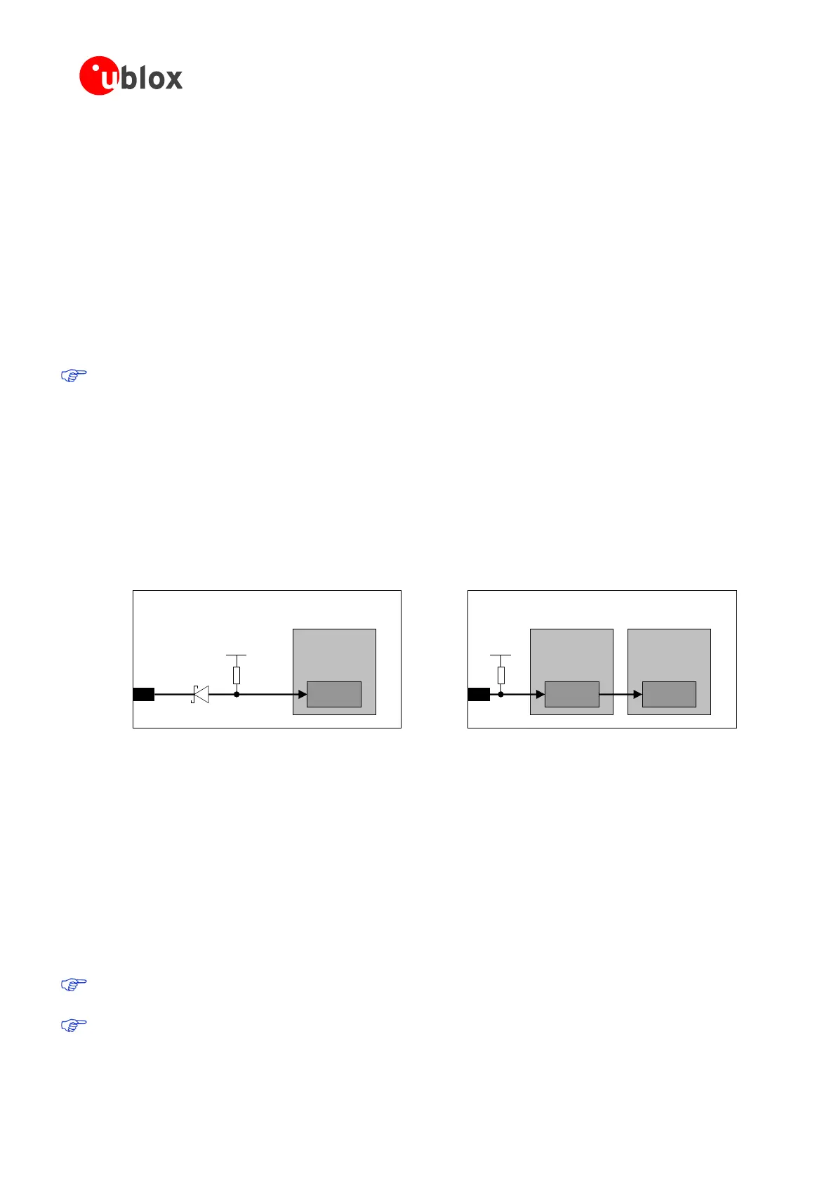
As described in Figure 24, both the SARA-G3 and SARA-U2 series modules are equipped with an internal pull-up
resistor which pulls the line to the high logic level when the RESET_N pin is not forced low from the external.
The pull-up is internally biased by V_INT on SARA-G3 modules and is biased by V_BCKP on SARA-U2 modules.
A series Schottky diode is mounted inside the SARA-G3 modules, increasing the RESET_N input voltage range.
See the SARA-G3 series Data Sheet [1] and the SARA-U2 series Data Sheet [2] for the detailed electrical
characteristics of the RESET_N input.
Baseband
Processor
18
RESET_N
SARA-U2 series
Reset
Power
Management
Reset
10k
V_BCKP
Baseband
Processor
18
RESET_N
SARA-G3 series
Reset
10k
V_INT
Figure 24: RESET_N input description
When a low level is applied to the RESET_N input, it causes an “external” or “hardware” reset of the modules,
with the following behavior of SARA-G3 and SARA-U2 series modules due to different internal circuits:
SARA-G3 modules: reset of the processor core, excluding the Power Management Unit and the RTC block.
The V_INT generic digital interfaces supply is switched on and each digital pin is set in its internal reset state.
The V_BCKP supply and the RTC block are switched on.
SARA-U2 modules: reset of the processor core and the Power Management Unit, excluding the RTC block.
The V_INT generic digital interfaces supply is switched off and all digital pins are tri-stated (not supplied).
The V_BCKP supply and the RTC block are switched on.
Before the switch-on of the generic digital interface supply source (V_INT) of the module, no voltage
driven by an external application should be applied to any generic digital interface of the modules.
The internal reset state of all digital pins is reported in the pin description table in the SARA-G3 series
Data Sheet [1] and in the SARA-U2 series Data Sheet [2].
 Loading...


