SARA-R4 series - System integration manual
UBX-16029218 - R20 System description Page 21 of 128
C1-Public
1.5 Supply interfaces
1.5.1 Module supply input (VCC)
The modules must be supplied via the three VCC pins that represent the module power supply input.
Voltage must be stable, because during operation, the current drawn by the SARA-R4 series modules
through the VCC pins can vary by several orders of magnitude, depending on the operating mode and
state (as described in sections 1.5.1.2, 1.5.1.3, 1.5.1.4 and 1.5.1.6).
It is important that the supply source is able to withstand both the maximum pulse current occurring
during a transmit burst at maximum power level and the average current consumption occurring
during Tx / Rx call at maximum RF power level (see the SARA-R4 series data sheet [1]).
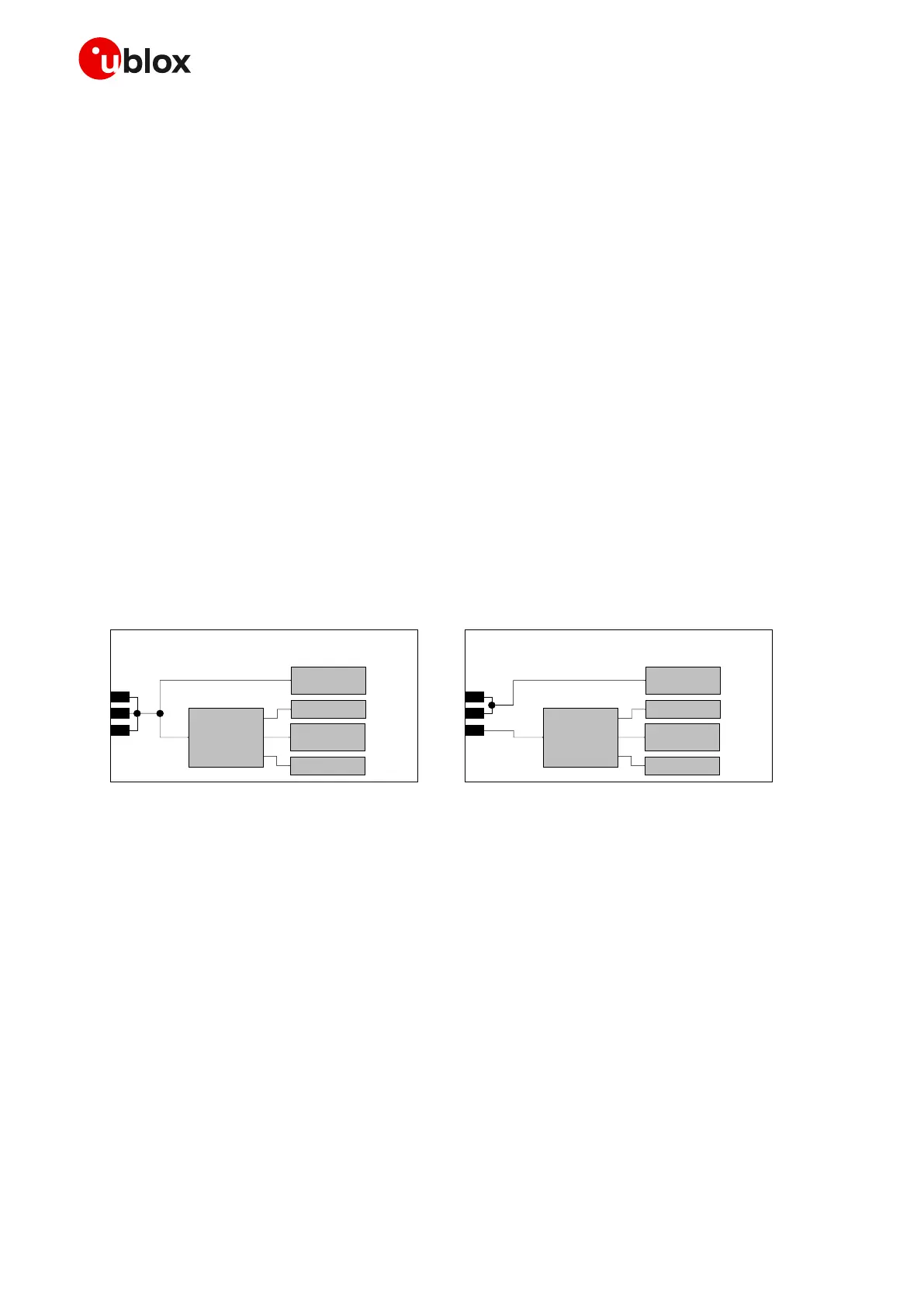
SARA-R412M, SARA-R422, SARA-R422S, SARA-R422M8S modules, supporting 2G radio access
technology, provide separate supply inputs over the three VCC pins:
• VCC pins #52 and #53 represent the supply input for the internal RF power amplifier, demanding
most of the total current drawn of the module when RF transmission is enabled during a call
• VCC pin #51 represents the supply input for the internal baseband power management unit,
demanding minor part of the total current drawn of the module when RF transmission is enabled
during a call
The 3 VCC pins of SARA-R410M modules are internally connected each other to both the internal RF
Power Amplifier and the internal baseband power management unit.
Figure 6 provides a simplified block diagram of SARA-R4 series modules’ internal VCC supply routing.
 Loading...


