SARA-R4 series - System integration manual
UBX-16029218 - R20 Design-in Page 59 of 128
C1-Public
2.3 System functions interfaces
2.3.1 Module PWR_ON / PWR_CTRL input
2.3.1.1 Guidelines for PWR_ON / PWR_CTRL circuit design
SARA-R4 series PWR_ON / PWR_CTRL input is equipped with an internal active pull-up resistor; an
external pull-up resistor is not required and should not be provided.
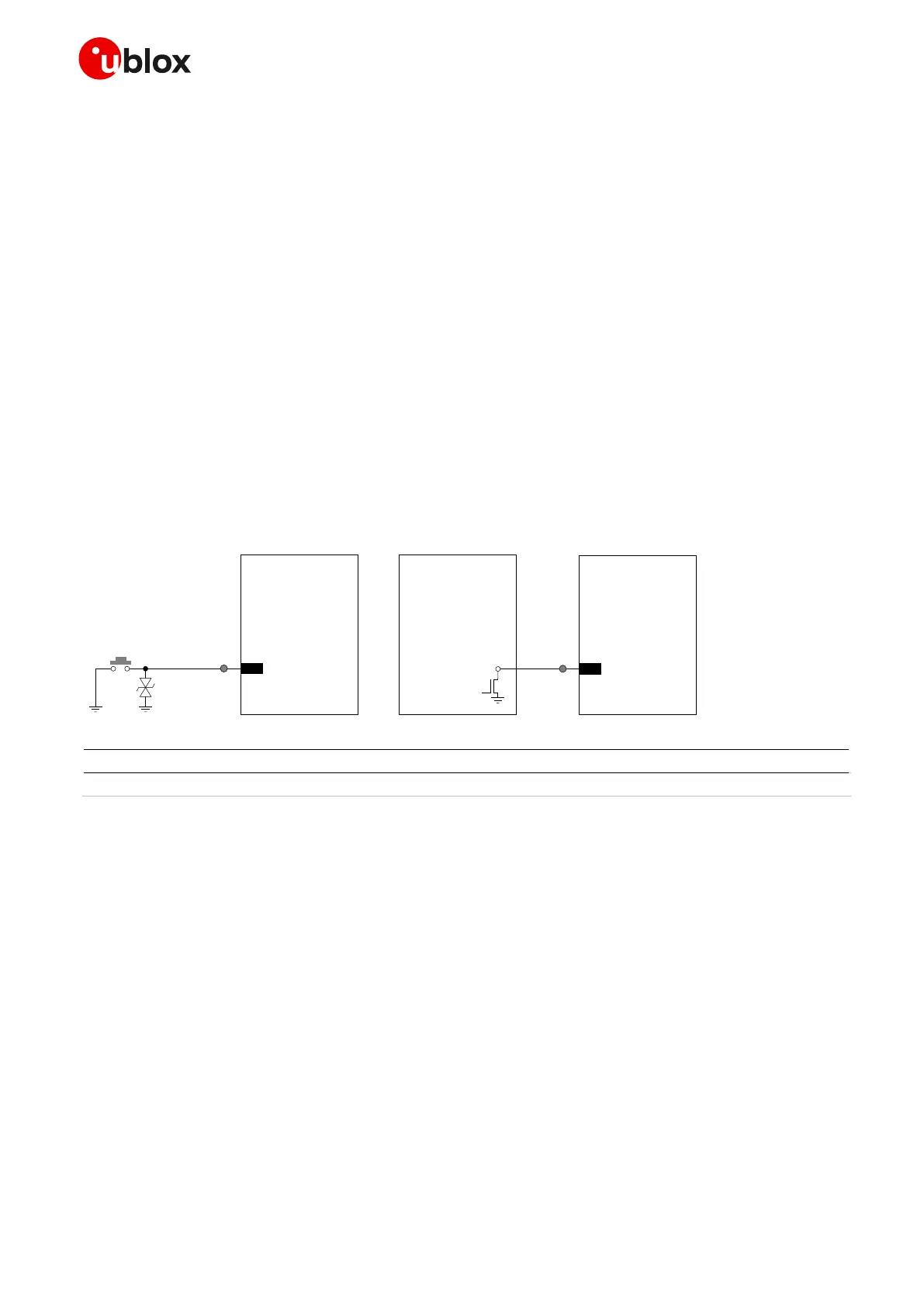
If connecting the PWR_ON / PWR_CTRL input to a push button, the pin will be externally accessible
on the application device. According to EMC/ESD requirements of the application, an additional ESD
protection should be provided close to the accessible point, as described in Figure 33 and Table 21.
☞ ESD sensitivity rating of the PWR_ON / PWR_CTRL pin is 1 kV (HBM according to JESD22-A114).
Higher protection level can be required if the line is externally accessible on the application board,
e.g. if an accessible push button is directly connected to the pin, and it can be achieved by
mounting an ESD protection (e.g. EPCOS CA05P4S14THSG varistor) close to the accessible point.
An open drain or open collector output is suitable to drive the PWR_ON / PWR_CTRL input from an
application processor, as described in Figure 33.
☞ PWR_ON / PWR_CTRL input line should not be driven high, as it may cause start up issues.
Table 21: Example ESD protection component for the PWR_ON / PWR_CTRL application circuit
☞ It is highly recommended to provide direct access to the PWR_ON / PWR_CTRL pin on the
application board by means of an accessible test point directly connected to the PWR_ON /
PWR_CTRL pin, for firmware upgrade and/or for diagnostic purposes
2.3.1.2 Guidelines for PWR_ON / PWR_CTRL layout design
The PWR_ON / PWR_CTRL circuit requires careful layout since it is the sensitive input available to
switch on and switch off the SARA-R4 series modules. It is required to ensure that the voltage level is
well defined during operation and no transient noise is coupled on this line, otherwise the module
might detect a spurious power-on request.
 Loading...


