SARA-R4 series - System integration manual
UBX-16029218 - R20 Design-in Page 61 of 128
C1-Public
2.4 Antenna interfaces
SARA-R4 series modules provide an RF interface for connecting the external antenna: the ANT pin
represents the RF input/output for RF signals transmission and reception.
SARA-R422M8S modules provide also a GNSS RF interface for connecting the external GNSS
antenna: the ANT_GNSS pin represents the GNSS RF input for GNSS signals reception.
The ANT and ANT_GNSS pins have a nominal characteristic impedance of 50 and must be
connected to the related external antenna system through a 50 transmission line to allow clean
transmission / reception of RF signals.
2.4.1 General guidelines for antenna interfaces
2.4.1.1 Guidelines for ANT and ANT_GNSS pins RF connection design
☞ The GNSS antenna RF interface is supported by SARA-R422M8S modules only.
A clean transition between the ANT and ANT_GNSS pads and the application board PCB must be
provided, implementing the following design-in guidelines for the layout of the application PCB close
to the ANT and ANT_GNSS pads:
• On a multilayer board, the whole layer stack below the RF connections should be free of digital lines
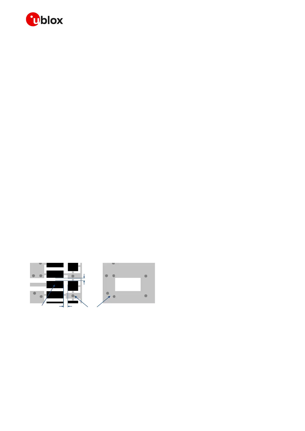
• Increase GND keep-out (i.e. clearance, a void area) around the ANT and ANT_GNSS pads, on the
top layer of the application PCB, to at least 250 m up to adjacent pads metal definition and up to
400 m on the area below the module, to reduce parasitic capacitance to ground, as described in
the left picture in Figure 35
• Add GND keep-out (i.e. clearance, a void area) on the buried metal layer below the ANT and
ANT_GNSS pads if the top-layer to buried layer dielectric thickness is below 200 m, to reduce
parasitic capacitance to ground, as described in the right picture in Figure 35
 Loading...


