SARA-R4 series - System integration manual
UBX-16029218 - R20 Design-in Page 94 of 128
C1-Public
2.6.5.2 Guidelines for DDC (I2C) layout design
The DDC (I2C) serial interface requires the same consideration regarding electro-magnetic
interference as any other digital interface. Keep the traces short and avoid coupling with RF line or
sensitive analog inputs, since the signals can cause the radiation of some harmonics of the digital
data frequency.
2.7 Audio
2.7.1 Guidelines for Audio circuit design
☞ Audio is not supported by current product versions: the I2S digital audio interface pins should not
be driven by any external device.
2.8 General Purpose Input/Output
2.8.1 Guidelines for GPIO circuit design
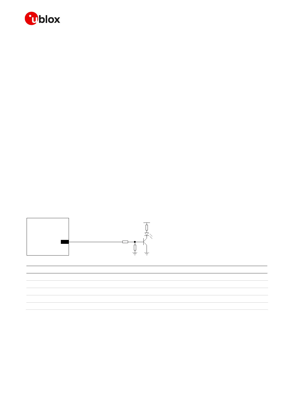
A typical usage of SARA-R4 series modules’ GPIOs can be the following:
• Network indication provided over GPIO1 pin (see Figure 65 / Table 46 below)
• GNSS supply enable function provided by the GPIO2 pin (see section 2.6.5)
• GNSS Tx data ready function provided by the GPIO3 pin (see section 2.6.5)
• Module operating status indication provided by a GPIO pin (see section 1.6.1)
• SIM card detection provided over GPIO5 pin (see Figure 50 / Table 37 in section 2.5)
Table 46: Components for network indication application circuit
☞ Use transistors with at least an integrated resistor in the base pin or otherwise put a 10 k resistor
on the board in series to the GPIO of SARA-R4 series modules.
☞ Do not apply voltage to any GPIO of the module before the switch-on of the GPIOs supply (V_INT),
to avoid latch-up of circuits and allow a clean module boot. If the external signals connected to the
module cannot be tri-stated or set low, insert a multi-channel digital switch (e.g. TI
SN74CB3Q16244, TS5A3159, TS5A63157) between the two-circuit connections and set to high
impedance before V_INT switch-on.
 Loading...


