SARA-R4 series - System integration manual
UBX-16029218 - R20 Design-in Page 88 of 128
C1-Public
2.6.2 USB interface
2.6.2.1 Guidelines for USB circuit design
The USB_D+ and USB_D- lines carry the USB serial data and signaling. The lines are used in single-
ended mode for full speed signaling handshake, as well as in differential mode for high speed signaling
and data transfer.
USB pull-up or pull-down resistors and external series resistors on USB_D+ and USB_D- lines as
required by the USB 2.0 specification [6] are part of the module USB pins driver and do not need to be
externally provided.
The USB interface of SARA-R410M and SARA-R412M modules is enabled only if a valid voltage is
detected by the VUSB_DET input (see the SARA-R4 series data sheet [1]). Neither the USB interface
nor the whole module is supplied by the VUSB_DET input: the VUSB_DET senses the USB supply
voltage and absorbs few microamperes.
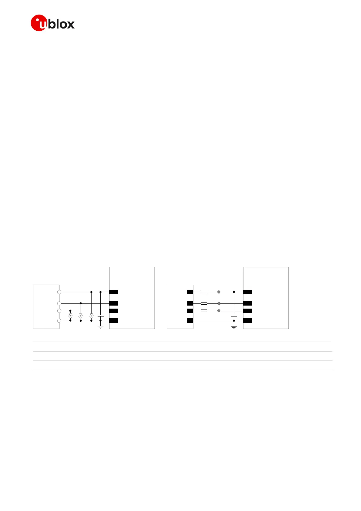
Routing the USB pins to a connector, they will be externally accessible on the application device.
According to EMC/ESD requirements of the application, an additional ESD protection device with very
low capacitance should be provided close to accessible point on the line connected to this pin, as
described in Figure 59 and Table 42.
☞ USB interface pins ESD sensitivity rating is 1 kV (HBM according to JESD22-A114F). Higher
protection level could be required if the lines are externally accessible and it can be achieved by
mounting an ultra low capacitance (i.e. < 1 pF) ESD protection (e.g. Littelfuse PESD0402-140 ESD
protection device) on the lines connected to these pins, close to accessible points.
The USB pins of SARA-R410M and SARA-R412M modules can be directly connected to the USB host
application processor without additional ESD protections if they are not externally accessible or
according to EMC/ESD requirements.
Table 42: Components for USB application circuits for SARA-R410M and SARA-R412M modules
☞ If the USB interface is enabled, the module does not enter the low power deep sleep mode: the
external USB VBUS supply voltage needs to be removed from the VUSB_DET input of the module
to let it enter the Power Saving Mode defined in 3GPP Rel.13.
☞ If the USB interface is not used with SARA-R410M and SARA-R412M modules, the USB interface
pins can be left unconnected on the application board, but it is strongly recommended to provide
accessible test points directly connected to the VUSB_DET, USB_D+, and USB_D- pins for FW
upgrade and/or for diagnostic purpose.
 Loading...


