SARA-R4 series - System integration manual
UBX-16029218 - R20 System description Page 28 of 128
C1-Public
1.6 System function interfaces
1.6.1 Module power-on
When the SARA-R4 series modules are in the not-powered mode (i.e. the VCC module supply is not
applied), they can be switched on as follows:
• Rising edge on the VCC input pins to a valid voltage level, and then a low logic level needs to be set
at the PWR_ON / PWR_CTRL input pin for a valid time.
When the SARA-R4 series modules are in the power-off mode (i.e. switched off) or in the Power Saving
Mode (PSM), with a valid VCC supply applied, they can be switched on as follows:
• Low pulse on the PWR_ON / PWR_CTRL pin for a valid time period
The PWR_ON / PWR_CTRL input pin is equipped with an internal active pull-up resistor. Detailed
characteristics with voltages and timings are described in the SARA-R4 series data sheet [1].
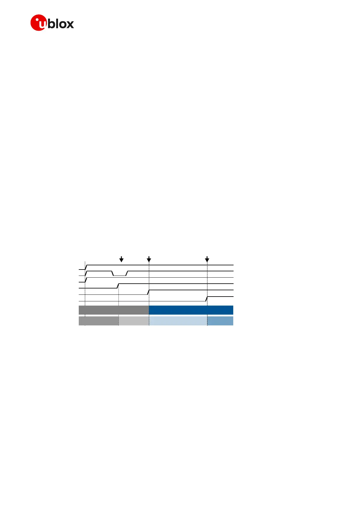
Figure 14 shows the module switch-on sequence from the not-powered mode, with following phases:
• The external power supply is applied to the VCC module pins
• The PWR_ON / PWR_CTRL pin is held low for a valid time
• All the generic digital pins are tri-stated until the switch-on of their supply source (V_INT).
• The internal reset signal is held low: the baseband core and all digital pins are held in reset state.
When the internal reset signal is released, any digital pin is set in the correct sequence from the
reset state to the default operational configured state. The duration of this phase differs within
generic digital interfaces and USB interface due to host / device enumeration timings.
• The module is fully ready to operate after all interfaces are configured.
Figure 14: SARA-R4 series switch-on sequence description
☞ The Internal Reset signal is not available on a module pin, but it is highly recommended to monitor:
o the V_INT pin, to sense the start of the SARA-R4 series module switch-on sequence
o the GPIO pin configured to provide the module operating status indication (see SARA-R4 series
commands manual [2], +UGPIOC AT command), to sense when the module is ready to operate
☞ Before the switch-on of the generic digital interface supply (V_INT) of the module, no voltage
driven by an external application should be applied to any generic digital interface of the module.
☞ Before the SARA-R4 series module is fully ready to operate, the host application processor should
not send any AT command over AT communication interfaces (USB, UART) of the module.
☞ The duration of the SARA-R4 series modules’ switch-on routine can largely vary depending on the
application / network settings and the concurrent module activities.
⚠ An abrupt removal of the VCC supply, or forcing an abrupt emergency reset / switch off by
asserting the RESET_N / PWR_CTRL input, once the boot of SARA-R4 series modules has been
triggered may lead to an unrecoverable faulty state!
 Loading...


