8
1.
2.
3.
4.
5.
6.
7.
8.
9.
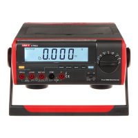
Model UT805: OPERATING MANUAL
1 2 3 4
5
6
789101112
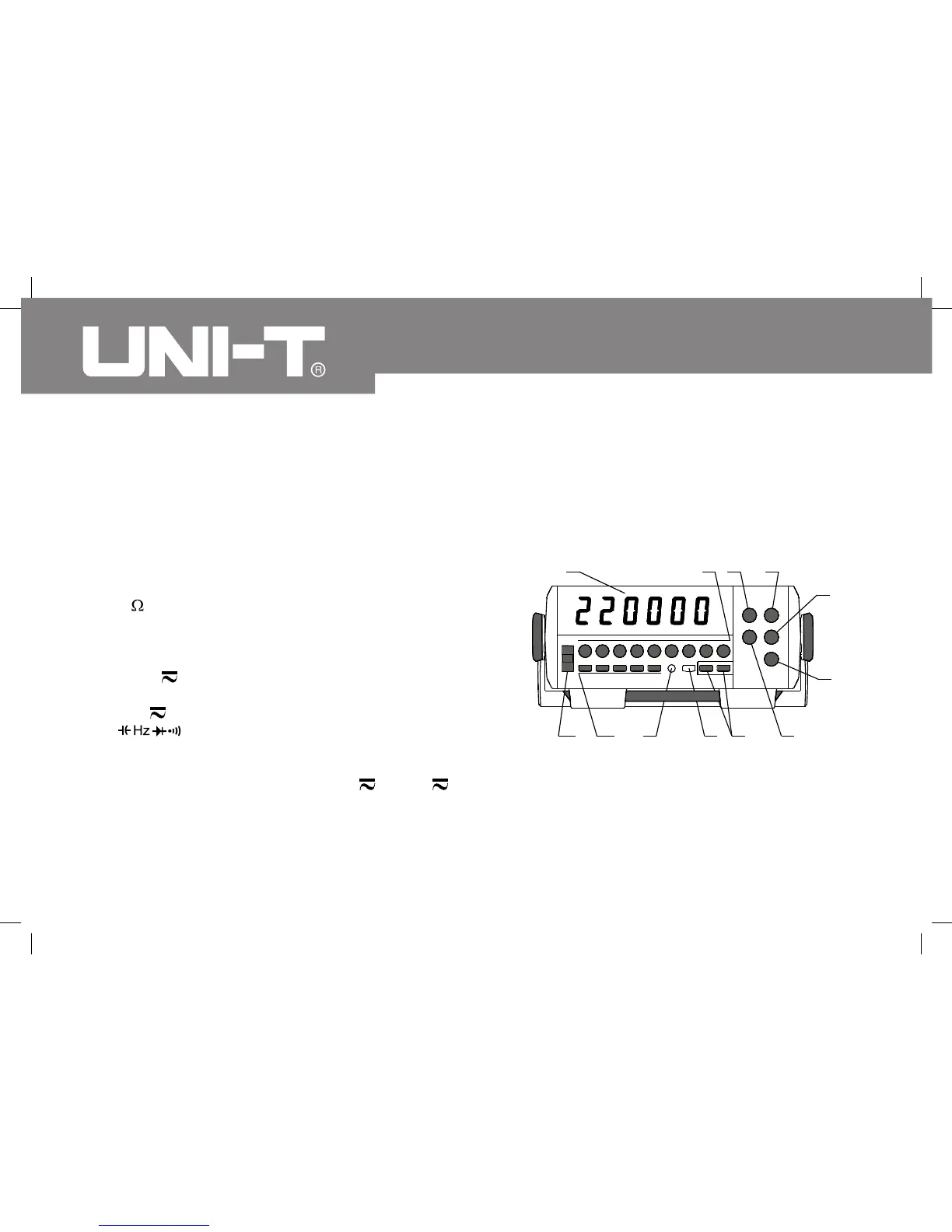
The Meter Structure
A. Front Panel (see figure 1)
VFD Display
Primary Functional Buttons: Different key functions
selection.
COM Input Terminal: Negative input terminal,
inserting the black test lead.
V/ Input Terminal: Positive input terminal for voltage
and resistance measurement, inserting the red test
lead.
200mA MAX Input Terminal: Positive input terminal
for mA measurement, inserting the red test lead.
6. 10A MAX Input Terminal: Positive input terminal
for A measurement, inserting the red test lead.
Input Terminal: Positive input terminal for
capacitance, frequency, diode and continuity
measurement, inserting the red test lead.
2mA and 200mA Buttons: mA and A
measurement selection
AC+DC Button: The measurement of AC voltage
or current with DC deviation.
(figure 1)
 Loading...