25
3.
4.
1.
2.
3.
4.
5.
6.
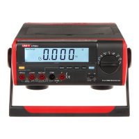
Model UT805: OPERATING MANUAL
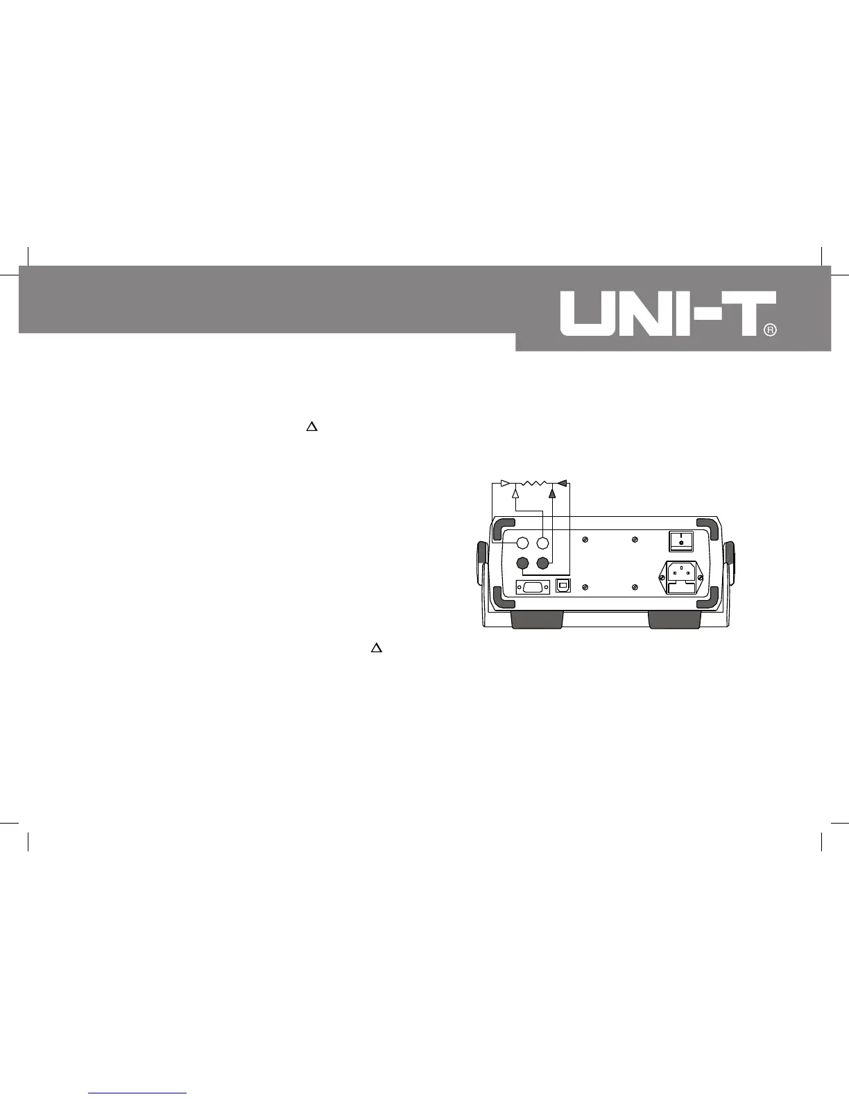
Rx
RL
L0
HI
To obtain more accurate readings, you could short-
circuit the test lead and press REL to display “0”
before carrying out measurement
Connect the test leads across with the object. The
measured value shows on the primary display and
the measuring range shows on the secondary display.
Four wire configuration measure resistance, connect
the Meter as follows: (see figure 8)
Use 2 sets of test lead and insert them into the rear
panel of the Meter.
Insert two red test leads into the two red terminals
at the rear panel.
Insert two black test leads into the two black terminals
at the rear panel
Short circuit the four test laads and press REL to
display “0”.
Connect the test leads across with the object. The
measured value shows on the primary display and
the measuring range shows on the secondary display.
Four wire configuration measuring resistance can
eliminate the influence of the test lead internal
resistance, it is suitable for testing small resistance.
(figure 8)
 Loading...