UTD1000 User Manual
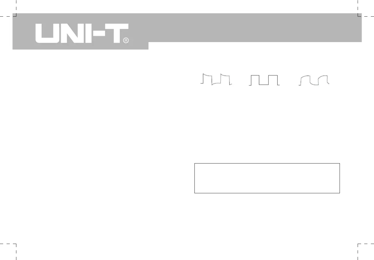
Over compensation Correct Compensatio Under compensation
Figure 1-6 Probe compensation calibration
If you see an "Under compensation" or “Over compens-
ation” waveform display, adjust the adjustable tab
of the probe with screwdriver with nonmetal handle
in the probe accessory pack, until a “Correct Com-
pensation” waveform shown in the above figure is dis-
played.
Warning : To avoid electric shock when measuring high
voltage with the probe, ensure the probe’s insulation
lead is in good condition. Do not touch the metal part of
the probe when connected to HV power.
4. Probe Compensation
When connecting the probe to any input channel for the
first time, perform this adjustment to match the probe to
the channel. Skipping the compensation calibration step
will result in measurement error or fault. Please adjust
probe compensation as follows :
1.Set the probe attenuation factor to 10X. Move the
switch on the probe to 10X and connect the probe to
Channel A. Connect the probe tip and ground clamp
to the output terminal of the function signal generator.
Select a square wave of 1kHz output frequency and
3Vpp amplitude. (Rising time of square wave should be
≤100 μs).
2.Turn Channel A on then press [AUTO].
3.Observe the shape of the displayed waveform.
 Loading...

