UTD1000 User Manual
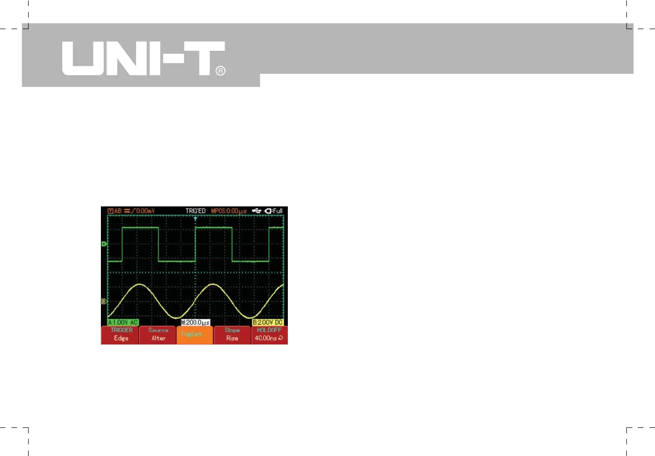
Alternate Trigger
When alternate trigger is selected, trigger signals will
be present in their individual vertical channels. This
triggering mode is suitable for observing two signals of
uncorrelated signal frequencies, as shown in the figure
below.
Figure 2-19 Alternate trigger
Alternate trigger can also be used to compare pulse
widths.
Definitions
1.Trigger source : Trigger can be obtained from various
sources : Input channel (A or B) and alternate.
Ƶ
Input Channel : The most common trigger source
is input channel (choose A or B). The channel selected
as trigger source can operate normally only when the
corresponding input channel is on.
2.Trigger mode : Determine the action of your
Oscilloscope at trigger by selecting the mode. This
Oscilloscope offers three trigger modes for selection :
auto, normal and single.
Ƶ
Auto Trigger : The system will acquire waveform
data automatically when there is no trigger signal input.
The scan baseline is shown on the display. When the
trigger signal is generated, it automatically turns to
trigger scan for signal synchronization.
Note : When time base of the scan range is set to
50ms/div or slower, the Oscilloscope will enter the “Scan”
mode.
Ƶ
Normal Trigger : In this mode, your Oscilloscope
samples waveforms only when triggering conditions are
met. The system stops acquiring data and waits when
 Loading...

