UTD1000 User Manual
display the circuit’s input and output characteristics in a
Lissajous figure.
8.Adjust the vertical amplitude range and vertical
position to achieve the best waveform.
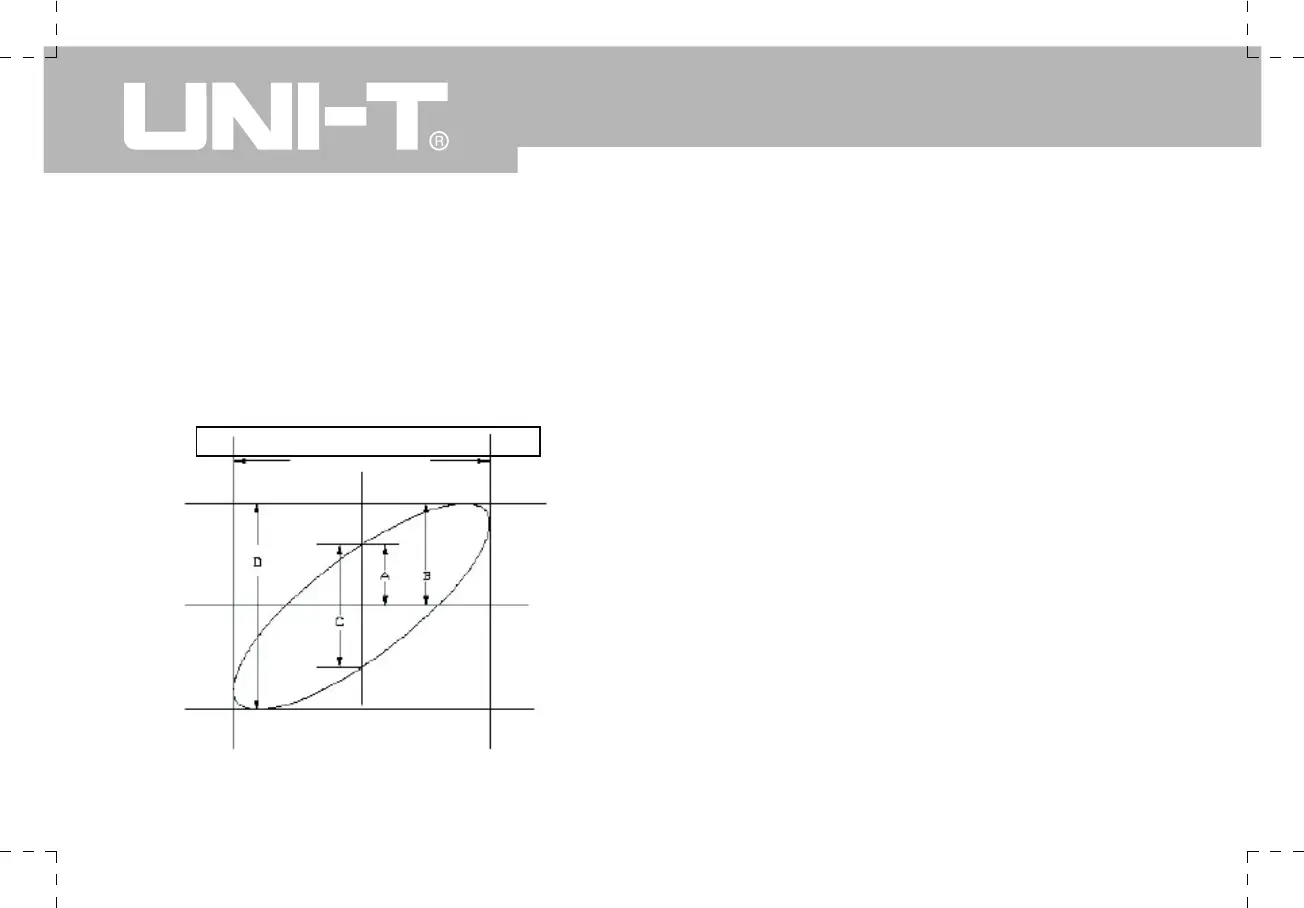
9.Using the elliptic Oscilloscope display graph to
observe, measure and calculate the phase difference.
(See the figure below)
If sin θ = A/B or C /D ,
θ is the angle of disparity between the channels.
For definitions of A, B, C, D see the above figure.
Calculating with this formula, the angle of disparity is
θ= ±arcsin (A /B) or θ= ±arcsin (C /D).
If the elliptic main axis is within quadrants I and III, the
angle of disparity should be within quadrants I and IV, i.e.
inside (0~ π/2) or (3π/2 ~ 2π).
If the main axis is within quadrants II and IV, the angle
of disparity should be within quadrants II and III, i.e.
inside (π/2 ~ π) or (π ~ 3π/2).
Furthermore, if the frequencies and phase differences
of two signals being measured are exact multiples,
you can calculate the frequency and phase correlation
between the two signals.
The signal must be horizontally center
Figure 3-7 Lissajous figure
 Loading...

