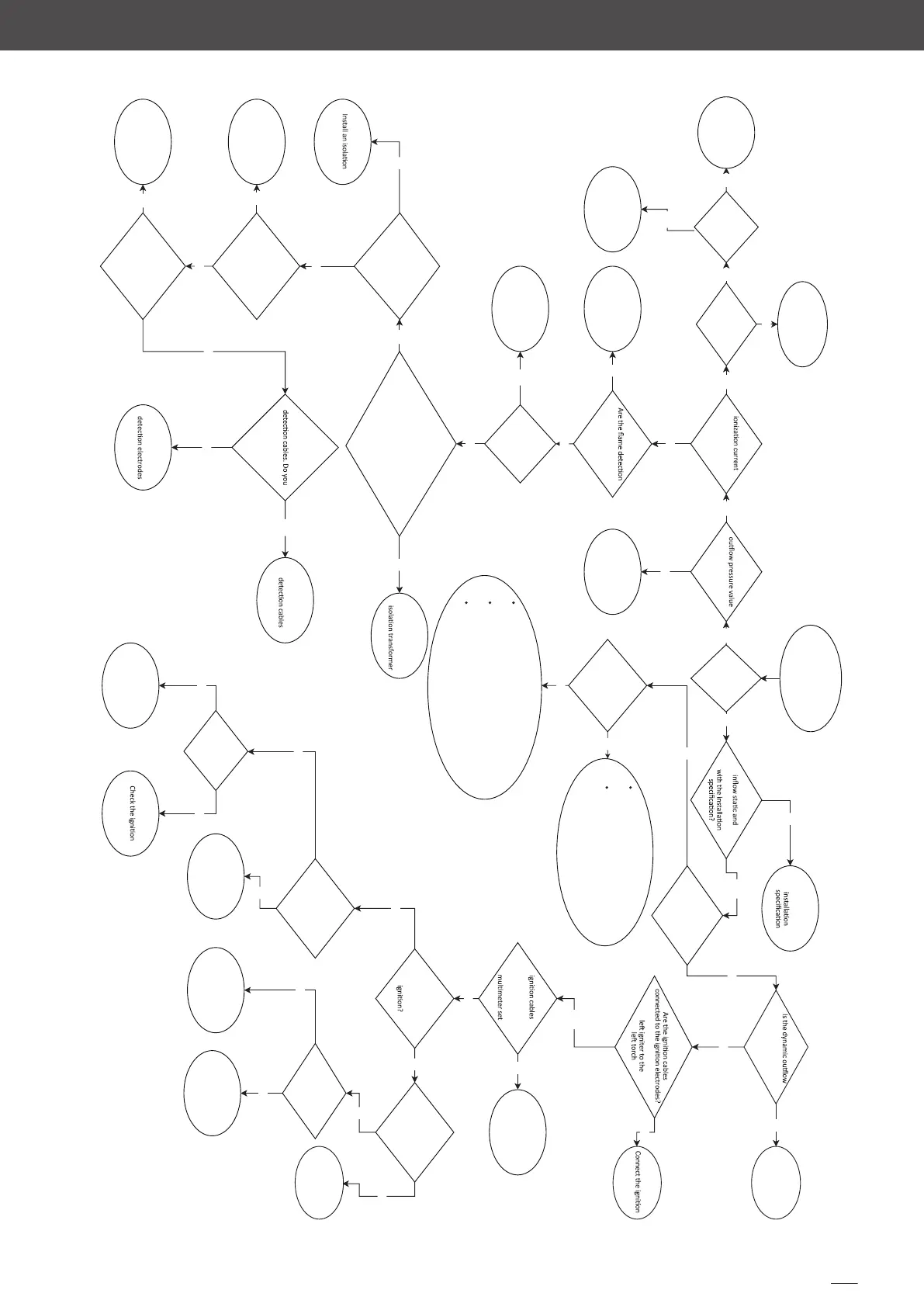
AF23.XY
Replace the Brahma
flame control board
Install the XRF013
sealing kit
Replace the back
power board
Is the problem
fixed?
Is there a voltage greater
than 80 VAC between pin
15 of J6 socket
and pin 11 of J4?
Is the power board
correctly connected to the
ground through
the metal
screws?
Is the flame detected in
both torches?
Check the flame
Swap the places
of the flame
have the issue on
the other
side?
Replace the flame
Upd
ate
the electrical
system or install an
transformer
Connect the board to
the ground by means
of the metal screws
Replace the Brahma
flame control board
Do you have the following value?
1. Phase-Neutral = 230 VAC
2. Phase-Ground = 230 VAC
3. Neutral-Ground = 0 VAC
Connect or replace
them
ca
bles click-clack style and
connected to the
electrodes?
Replace the gas
valve
Is the
re
220-240 VAC
betwee
n pin
8 and 10
of the J5 socket of the
Brahm
a fla
me control
board?a?
Is there humidity
out of the
torches?
Turn the plug
180 degrees.
Is the problem
fixed?
Is the
value stabl
e and within
the range 1,5
a
nd 10
uA DC?
Is
the dynamic
within the range
-0,7 e +
0,7 mbar?
Are you
able to feel
hot air coming out
from both the
burner
chimneys?
Does the
dyna
mic gas pressure comply
Is the gas valve supplied
with 190-210 V DC
?
Right igniter to the right torch,
cables
Do the
have a resisten
ce of 7-9
k
Ohm? Measure the
value with the
to ohm
Repl
ac
e the
damaged cable
Does
the c
on
tactor t
ha
t
commands the ignitors
trigger dur
ing the
Is there power supply
between pin A1 and
A2
of the contactor?
Replace the
contactor
Is the
re
220-240 VAC
between J2 and J3
socket of
the flame
contr
ol board?
Replace the
c
ontactor power
suppl
y cable
Repl
ac
e
the Brahma
flame contr
ol board
Restore the cable
harness
Are the igniters
connected through the
contactor to the power
supply?
Do you
hear the spark
during the start
up phase
?
electrodes
Replace the XRF011
kit
There is 220-240 VAC between pin 15 and
16 of the J6
so
cket of the flame control
board --> replace the flame control board
There is NOT 220-240 VAC between pin 15
and 16 of the J6 socket of the flame
c
ontrol
board --> check the power supply on the
te
rminal block and if there is power supply
from
P
22
so
cket of t
he power board
P34 socket of the power board is supplied, but there is
no voltage on P35 and P36 sockets --> replace the
power boa
rd
P34
socket of the power board is supplied and th
ere is
voltage on P35 and P36 --> replace the ga
s valve cable
harnes
s
P34 socket of the power board is no
t supplied -->
replace the cable between P34 and J5 socket of the
flame control board
Replace the back
power board
Conform the gas
sys
tem
to the
pressure value within the
range -0,7 e +0,7 mbar?
Replace the
blower+gas valve kit
YES NO
NO
YES
NO
YES
NO
NO
YES
YES
NO
YES
NO
NO
YES
YES
NO
NO
YES
NONO
YES
YES
NOYES
YES
NO
NO
YES
NO
NO
YES
NO
NO
YES
YES
NO
NO
YES
YES
NO
YES
YES
YES
YES
NO
OVEN
Turn the plug
180 degrees.
 Loading...