Seismic Detectors Application Guide
Table 6-1: Manually calculated detector locations
Table 6-1 is using the same dimensions and radius as per previous example (l= 25m; h= 3m; r=
4m). The calculated number of 5 detectors is the minimum number of detectors required to provide
100% coverage of the protected surface. The sum of the calculated distances d1 and sd
max
already
exceeds the length of the wall (highlighted in yellow). However, using four detectors would only
cover 24.4m of the protected surface and therefore would leave 0.6m exposed to potential intruder
attacks. Adding a fifth detector is required to ensure 100% detection coverage.
For maximum performance and efficient coverage, the calculated number of detectors
n can never be reduced.
Table 6-2: Manually balanced detector locations
In Table 6-2 the balanced detection layout uses the same number of detectors n. The calculated
distances d1, sd and d2 are reduced to fit within the length of the protected space (highlighted in
yellow). A schematic layout of the manually balanced system design is shown in Figure 6-4.
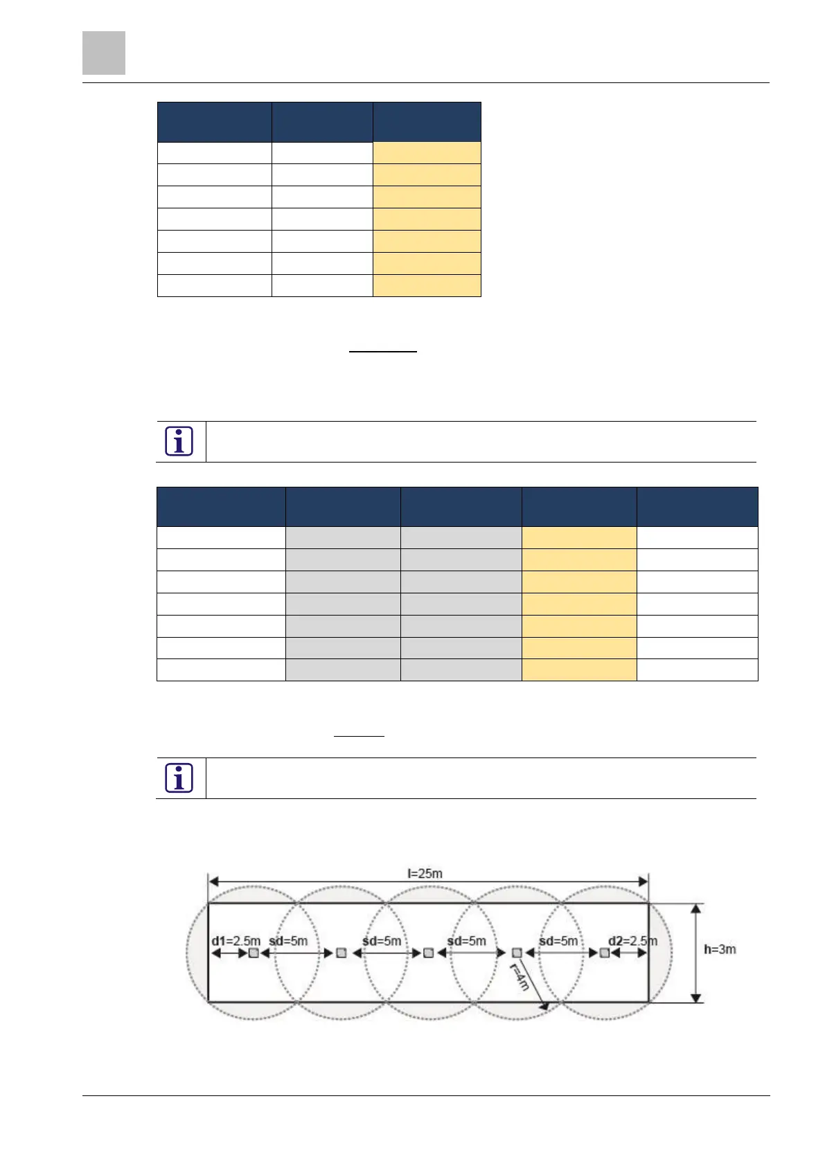
To balance a system design, the distances d1, d2, and sd may be reduced but never
increased.
Figure 6-4: Manually balanced detector locations with 5 detectors
Figure 6-4 shows the manually balanced system layout as per Table 6-2.

 Loading...
