46
10 Diagnostics and servicing
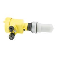
VEGABAR 39 • Three-wire 1 x transistor or 4 … 20 mA
57536-EN-200831
Sinceweoerthisserviceworldwide,thesupportisprovidedin
English. The service itself is free of charge, the only costs involved are
the normal call charges.
10.3 Diagnosis, fault messages
Connect a multimeter in the suitable measuring range according to
the wiring plan. The following table describes possible errors in the
current signal and helps to eliminate them:
Error Cause Rectication
4 … 20 mA signal not
stable
Fluctuating measured value Set damping
4 … 20 mA signal miss-
ing
Electrical connection faulty Check connection, correct, if necessary
Voltage supply missing Check cables for breaks; repair if nec-
essary
Operating voltage too low, load resist-
ance too high
Check, adapt if necessary
Short-circuit Check, repair if necessary
Current signal great-
er than 22 mA, less than
3.6 mA
Sensor electronics defective Replace device or send in for repair de-
pending on device version
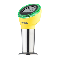
The LED illuminated ring on the device (see chapter " Conguration")
indicates the status of the device. At the same time it indicates the
switching state of the transistor output. This enables simple on-site
diagnosis without the need for tools.
Note:
The LED illuminated ring is not available for device versions with
continuous stainless steel housing.
Colour
6)
Permanent light Flashing Transistor output 1
Green voltage supply on, operation with-
out failure
Message "
Maintenancere-
quired" is displayed
open (high-resistance)
Yellow voltage supply on, operation with-
out failure
- closed (low-resistance)
Red voltage supply on, operation with
failure
Message acc. to to NE 107 "
Function check", " Out of speci-
cation" or " Simulation state" is
displayed
open (high-resistance)
10.4 Status messages according to NE 107
The instrument features self-monitoring and diagnostics according
to NE 107 and VDI/VDE 2650. In addition to the status messages in
the following tables there are more detailed error messages available
under the menu item " Diagnostics" via the respective adjustment
module.
4 … 20 mA signal
LED illuminated ring
6)
Adjustable via VEGA Tools app or PACTware/DTM
 Loading...