_________________________________________________________________________________________________________________________________________________________
*The pictures may differ depending on the type of PersonalScope
16
THE SIGNAL MARKERS
The user can perform measurements on a certain signal by using the four moveable markers. This can be
useful when measuring the interval between two points or the amplitude of any given peak.
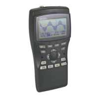
The following indications will appear on the screen:
1. The time interval between two vertical markers.
2. The calculated frequency 1/Dt (primarily used for
the measurement of periods).
3. The voltage between two horizontal markers.
4. Small dots indicating relative marker position on
the complete signal. (Just for HPS40)
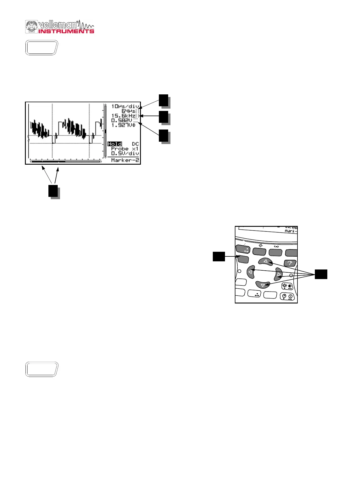
The markers can be moved through the arrow keys.
Keeping the key pressed down will move the marker
quickly, pressing it briefly will move the marker by 1
position. The “mark 1-2” key is used to select the
desired marker.
F Determining the frequency of a signal requires the measurement of a period. The easiest way to do
this would be by placing the vertical markers either on two consecutive peaks or two identical slopes
of a signal.
Press the “Marker 1-2”- key to view, select or hide the markers. (1)
Press the cursor keys to move the markers. (2)
G Notes:
• By pressing the ‘Marker 1-2’-key, you select between marker 1 or
2. The screen shifts automatically until the selected time marker is
on screen.
• At dynamic display mode (see display set-up), the best display
layout is chosen depending the use of time markers or voltage
markers.
• Some meter readouts are replaced by the marker readouts.
• Depending on the chosen display layout, not all of the marker readouts can be displayed at the same time.
• Removing the markers from the screen can be done by repeatedly pressing the ‘Marker 1-2’-key or by a short
press of the ‘Display’-key and using the up/down cursor keys.
SIGNAL SCREEN
Press first the X/Y-pos key before pressing the arrow keys in order to move the signal in the
direction of the arrows. Prolonged pressing will make the X or Y- position change faster.
A black bar (1) indicates the relative position of the signal in the sample window, see fig. 30. (Only for HPS40)
Just for HPS10:
A small dot in the left-hand corner of the screen will indicate the direction in which the signal has moved.
In this manner the user will know in which direction the signal was going when it went off-screen.
Marker
1 - 2
Fig 28
1
2
3
4
Fig 29
trigger
t-V/div
Memory
Display
setup
ac/dc
Gnd
Auto
Reset
Charge
Slope
Trigger
mode
Marker
1 - 2
1
2
X/Y-pos
 Loading...