_________________________________________________________________________________________________________________________________________________________
The pictures may differ depending on the type of PersonalScope
9
USE
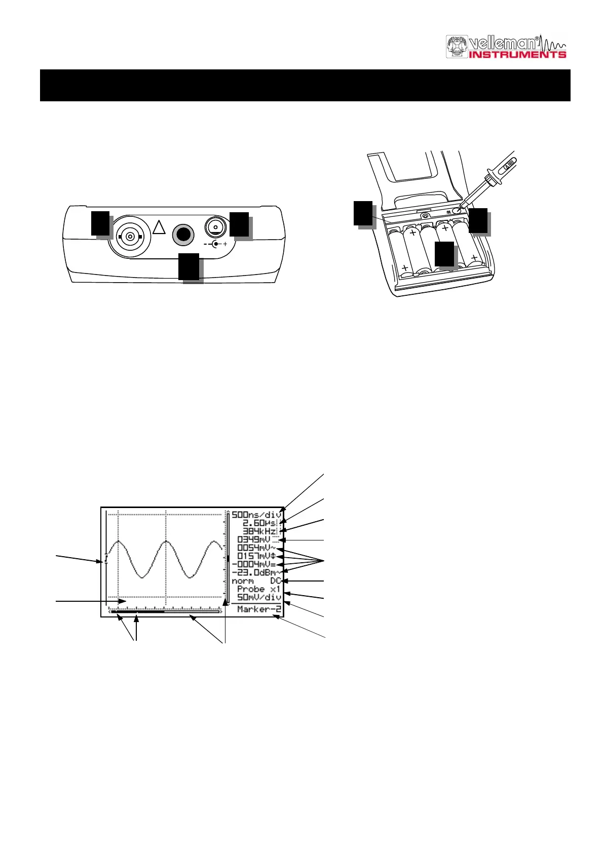
Survey of the connections and controls
1. BNC input connector (max. input 100Vp AC+DC).
2. Adapter connection (observe the polarity!)
3. RS232 output connector (optical isolated). Use the supplied RS232 cable, settings are: 57600 Baud,
8 data bits, no parity, 1 stop bit, no handshake. (Only for HPS40)
4. Battery compartment.
5. X10 probe testing signal behind battery cover.
6. Serial number.
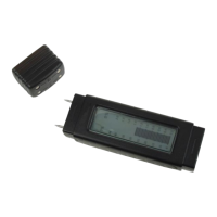
Survey of the indications on the screen:
1. Relative position indication of the signal
in the window. (Not for HPS10)
2. Trigger position and slope
indication.
3. Signal window with (possibly) the
markers or grid to indicate the
various divisions.
4. Time per division.
5. Time between markers (if present).
6. Calculated frequency 1/dt between
markers (if present).
7. Voltage between the markers (if
present).
8. Measurement readout. Depending on screen layout. See page 10.
9. Trigger information or screen hold indication, input-coupling indication.
10. X1 or X10 probe setup indication.
11. Selected voltage per division.
12. Indication of the selected cursor key function or battery-low indication.
13. Small dots indicating relative marker position (only if markers are present). (Not for HPS10)
probe
test
x10
4
123456
6
Fig 7.0
5
3
Fig 6.0
!
9V DC
I/O
1
2
Fig 8.0
2
3
4
5
6
7
8
9
10
11
12
 Loading...