42
Group 21 Short block
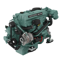
3. Check that the markings on the piston crown or
inside the piston line up with those on the con rod.
Use a piston ring compressor and install the pis-
ton with con rod in its cylinder, starting with cylin-
der no. 1 (forwards).
The con rod with the lowest number shall be
mounted first (in cyl. no. 1) and the con rod with
the highest number closest to the flywheel.
The con rods shall be turned so that the mark
(number/colorsplash) is facing “towards the injec-
tion pump” (camshaft side).
4. Mount the bearing cap and tighten the con rod
bolts. Tightening torque, please refer to the “Tech-
nical Data” chapter. Bearing caps must be in-
stalled so that the number markings/paint marks
on con rod and cap coincide.
Undamaged con rod bolts do not need to be
changed, they can be put back again.
5. Mount the oil suction pipe and oil strainer. Tight-
ening torque, please refer to the “Technical Data”
chapter. Use a new O-ring.
6. Install the sump with a new gasket. Tightening
torque, please refer to the “Technical Data” chapter.
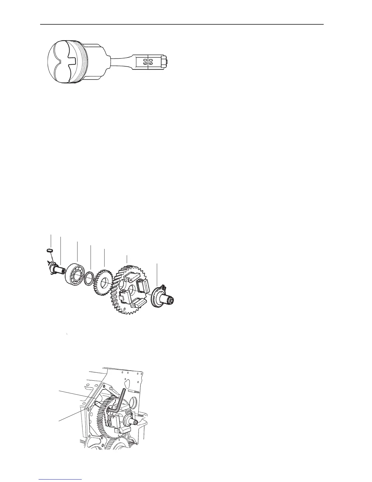
Installing the camshaft
The parts of the camshaft are mounted as illustrated.
1. Woodruff key 5. Gear wheel
2. Camshaft 6. Camshaft gear
3. Bearing 7. Regulator sleeve
4. Spacer
A
B
1. Install the front plate (A) with a new gasket. Tight-
ening torque, please refer to the “Technical Data”
chapter.
2. Oil the camshaft bearing surfaces and carefully
lift the camshaft into place, complete with drive
gear and regulator weights.
Note. Be careful to avoid damaging the bearings,
bearing tracks and camshaft lobes.
3. Install the camshaft lock washer (B) in the correct
position and tighten it. Tightening torque, please
refer to the “Technical Data” chapter.
2
6
4
5
3
7
1
 Loading...