92
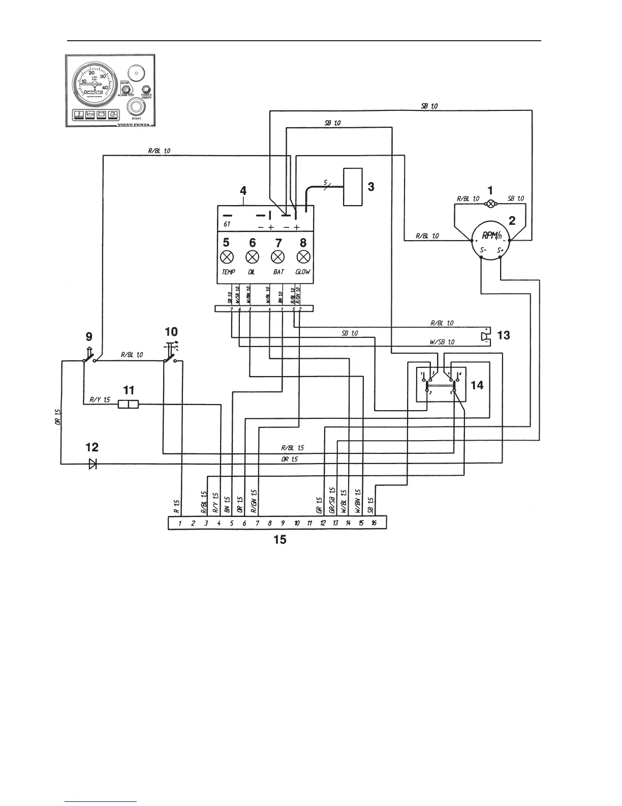
Group 30 Electrical system
1. Instrument illumination
2. Tachometere with built-in running hours timer (extra equip.).
Or blanking plug
3. Connector for connecting extra warning display
(optional equipment)
4. Electronic unit (alarm)
5. Warning lamp, coolant temperature
6. Warning lamp, oil pressure
7. Charge warning lamp
8. Indication lamp, glow plugs
9. Starter button
10. Press switch. Instrument panel On/Off
11. Connector for connecting extra neutral position switch
(optional equipment)
12. Semiconductor diode
13. Alarm
14. Tumbler switch. Glow – Alarm test/Acknowledge
15. 16-pin connector
Cable colors
BL = Blue
BN = Brown
GN = Green
GR = Gray
OR = Orange
PU = Purple
R = Red
SB = Black
W = White
Y = Yellow
Cable cross section in mm
2
is given after the color
code on the wiring diagram.
Instrument panel, alternative “A” *
* (without starter switch)
 Loading...