D
Group 177 Preventive Maintenance
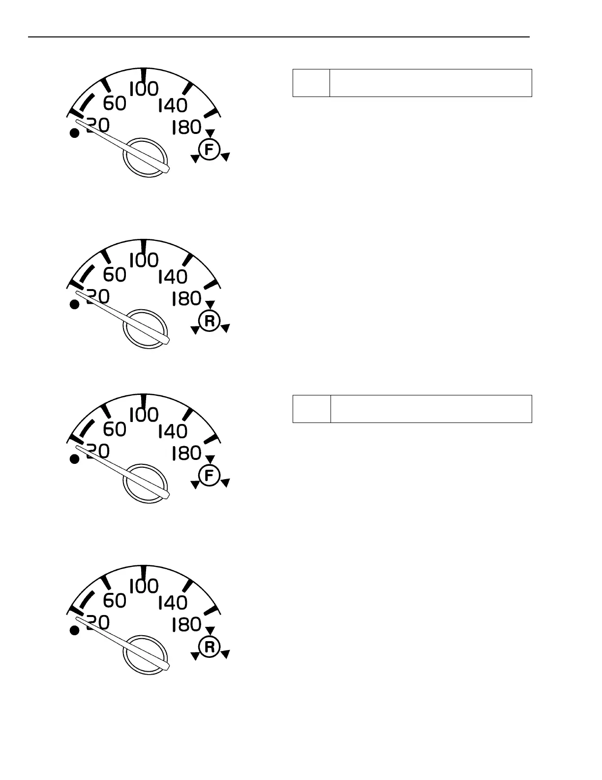
Front Brake Air Pressure Gauge
Rear Brake Air Pressure Gauge
28
Check Pressure Regulator’s Disconnection
and Connection Pressure
Pump the brake pedal while observing the air gauges.
As the air pressure is lowering, verify the compressor
governor cut-in pressure and the low air warning switches
cut-in pressure. Check that both indicator lights in the
lower right corner and the Master Warning indicator lights
up and make sure the buzzer sounds.
Governor cut-in should be at 790 ± 35 kPa (115 ± 5 psi).
The low air warning switches should close at a minimum
pressure of 420 kPa (60 psi).
Front Brake Air Pressure Gauge
Rear Brake Air Pressure Gauge
29
Check Air Compressor’s Function and
Condition
Raise the air pressure until it is 585 kPa (85 psi). Time
the air pressure build time from that point with the engine
at full speed. The pressure should reach 690 kPa (100
psi) in 25 seconds or less. Verify that the governor cutout
is at 900 ± 35 kPa (130 ± 5 psi).
Listen for unusual noises from the compressor while it is
running under load and unloaded.
When the governor cuts out, check for air dryer exhaust
function by listening for the air release from the air dryer
through the door or window.
58
 Loading...