4A-1
50 HZ PORTABLE GENERATORS G2.1A/G2.1AE 4A
4.1 Theory of Operation – Capacitor Generators
Brushless Generator
This model generator uses a brushless design to generate
and regulate power. It consists of a rotor, stator, diodes,
and an auxiliary winding. The brushless generator also
contains a capacitor that is connected to the auxiliary
winding. Its purpose is to regulate the voltage in the main
windings and prevent a voltage drop when a load is
applied.
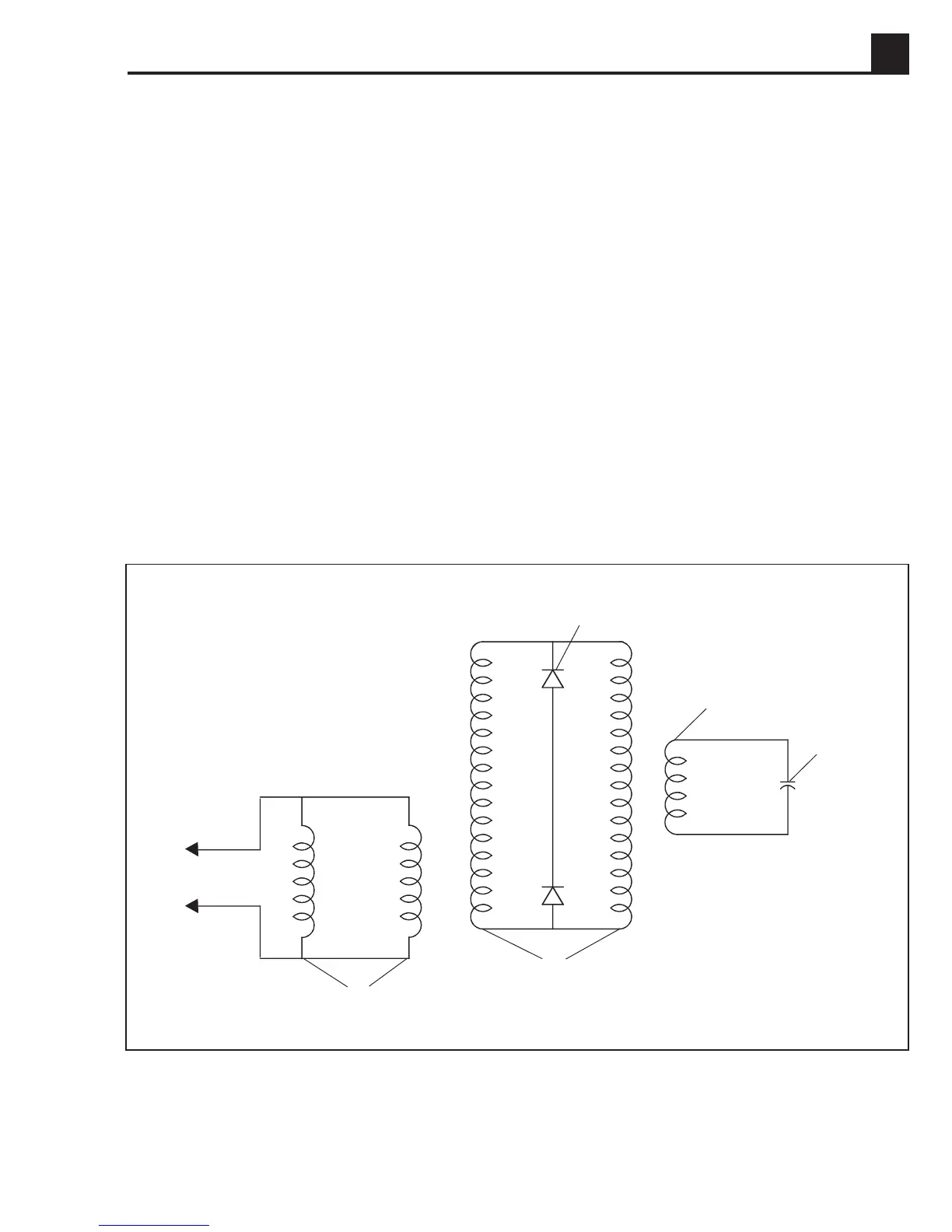
This generator is designed to operate with single phase
loads at or near a power factor of 1.0. The principle of
operation is schematically represented in Figure 4-1, and
a cross-sectional view in Figure 4-2. The auxiliary
winding (a), in conjunction with the capacitor, provide
excitation by inducing current in the rotor windings (b)
which is rectified by the diodes (c) to produce direct
current. The main stator winding (d) is designed for
parallel connection to give a voltage output with no
voltage adjustment possible.
Figure 4-1. Principle of Operation Schematic
1023SD44
d
Main Windings
b
Rotor Field
Windings
Capacitor
a
Auxiliary Winding
c
Diodes
(Rectifier)
Basic Generator Theory
Wacker air-cooled generators work on the principle of
electromagnetic induction i.e., the cutting of magnetic
lines of force by a coil of wire to produce an electric
voltage in the coil of wire.
The two main components of the generator, the rotor and
stator, are the key. The rotor acts as the magnet and the
stator acts as the coil of wire. As the rotor rotates, its
magnetic lines of force are cut by the coils of wire in the
stationary stator. The voltage induced in the windings of
the stator is tapped off and available at the receptacles.
 Loading...