4A-6
4A G2.1A/G2.1AE 50 HZ PORTABLE GENERATORS
4.11 Receptacle Panel Wiring
Remove receptacle panel from control box and inspect
the wiring for worn or loose wires. Make sure all wire
connections are secure and tight at the screws. DO NOT
allow wires to be pinched, kinked or damaged in any
way. Inspect for tight connections at circuit breakers,
capacitors, switches and receptacles. Replace any
broken or damaged parts.
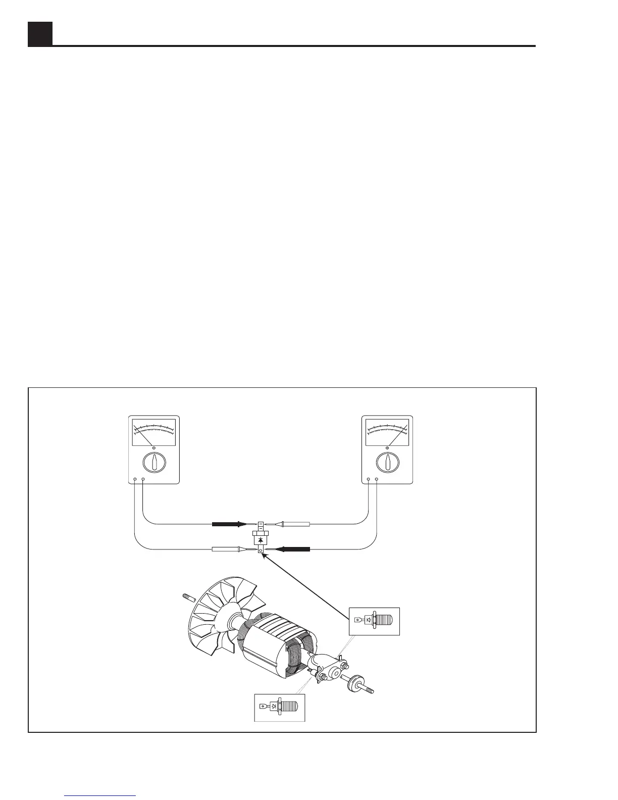
Figure 4-7. Rotor Diode Testing
1024SD03
A zero reading in both directions indicates a shorted
diode. A reading of Infinity in both directions indicates an
open diode. The diode must be replaced in either case.
If one diode is defective it is recommended that both
diodes be replaced since the remaining diode may have
been weakened.
To remove diode, use a soldering iron to soften solder
and remove wires.
When soldering on wires do not allow soldering iron to
remain on diodes longer than 10 seconds or diode may
be damaged.
4.12 Rotor Diode Testing
To check diode:
1. Disassemble generator and remove rotor. See Section
4.15
Generator Disassembly
.
2. Set ohmmeter in lowest scale. Test diode in forward
position. Meter should read low or close to zero.
3. Reverse meter leads and test diode in reverse position.
Meter should read high or close to infinity.
HIGH VALUE
LOW VALUE
 Loading...