5A-13
50 HZ PORTABLE GENERATORS G3.3A/G4.6A/GS4.6A/GS5.7A 5A
5.18 Generator Disassembly
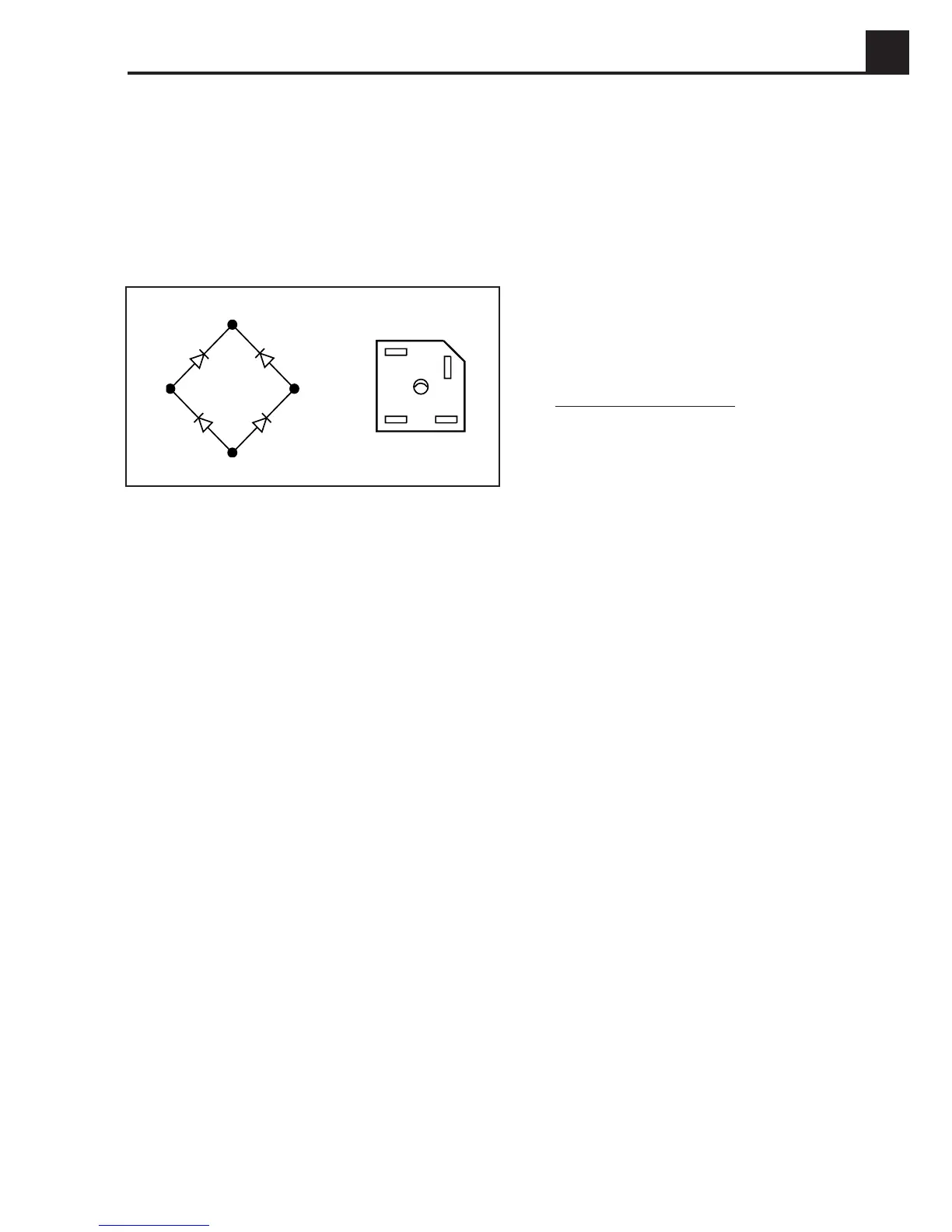
Bridge Rectifier
1. Remove the two end cover screws (19) and the end
cover (20). See Figure 5-16.
2. Remove the four leads from the bridge rectifier
(16)
confirming lead markings per Figure 5-17.
Figure 5-17. Diode Bridge Rectifier
3. Remove the choke/rectifier mounting screw (15).
Choke
1. Remove the bottom mounting screw (17) and care-
fully pull choke assembly (18) away from stator (14).
See Figure 5-16.
2. Disconnect the two leads (Z1 & Z3).
Fuel Tank and Control Box
1. Remove the fuel tank mounting bolts and tilt the tank
to gain access to the gas line and shut off valve.
2. Close the fuel valve and disconnect the fuel line.
Remove the fuel tank.
3. Remove the screws that mount the control panel to
the control box, and disconnect the harnesses and
ground wire from the control panel. Set the control
panel aside.
4. Remove the screws that mount the control box to the
generator and set control box aside.
Automatic Voltage Regulator (AVR) and
Brush Assembly
Disconnect the leads from the AVR (24) and brush
holder (23).
1. Remove the mounting screw (21), AVR (24) and
brush holder (23).
2. Remove 3 mounting screws
(25).
3. If brushes
(22) are to be changed, remove the brush
terminal plate and withdraw springs and brushes.
New brushes must be seated using a medium grade
abrasive cloth.
Stator
1. Remove the shaft securing nut (7).
2. Remove the four nuts (11) from the four studs (2)
securing the generator frame (14) to the engine
adapter flange (1).
3. For units with electric start:
A. Disconnect the negative lead from the battery
terminal first, and then the positive lead.
B. Loosen battery mounting bracket nuts and slide
mounting bracket off the battery.
C. Remove battery and store in cool dry place.
4. Remove the two bolts (30) and nuts (31) that mount
the stator (14) to the lifting bracket (10). Remove the
two bolts (30) and nuts (31) that mount the other end
of the stator (14) to the shock mounted support.
5. With a block of wood and a mallet, tap stator frame
away from the engine. Withdraw stator frame assembly
(14) over the rotor (4) carefully to avoid damage to
windings in the stator or rotor.
Note:
On some occasions, the rotor may come out with
the stator. If it does, skip step 6.
6. Support the rotor weight with a sling or place a block
between the rotor and base.
Rotor
Rotor (3) removed with stator:
1. Place stator (14) on flat surface with bearing (8) end
up. Elevate the stator by placing two blocks of wood
on the edge of the stator frame to allow the rotor to
drop.
2. Partially screw one of the frame mounting bolts into
the bearing and tap screw with a mallet. The rotor
should drop out of the stator.
Rotor (3) still attached to the engine:
1. Remove stator per instructions above.
2. Release the rotor (3) from the engine shaft by sup-
porting rotor in one hand and with a mallet, striking
firmly on a pole face.
Z2F2
Z3
F1
F2
F1
Z3
Z2
1023SD53
 Loading...