5A-17
50 HZ PORTABLE GENERATORS G3.3A/G4.6A/GS4.6A/GS5.7A 5A
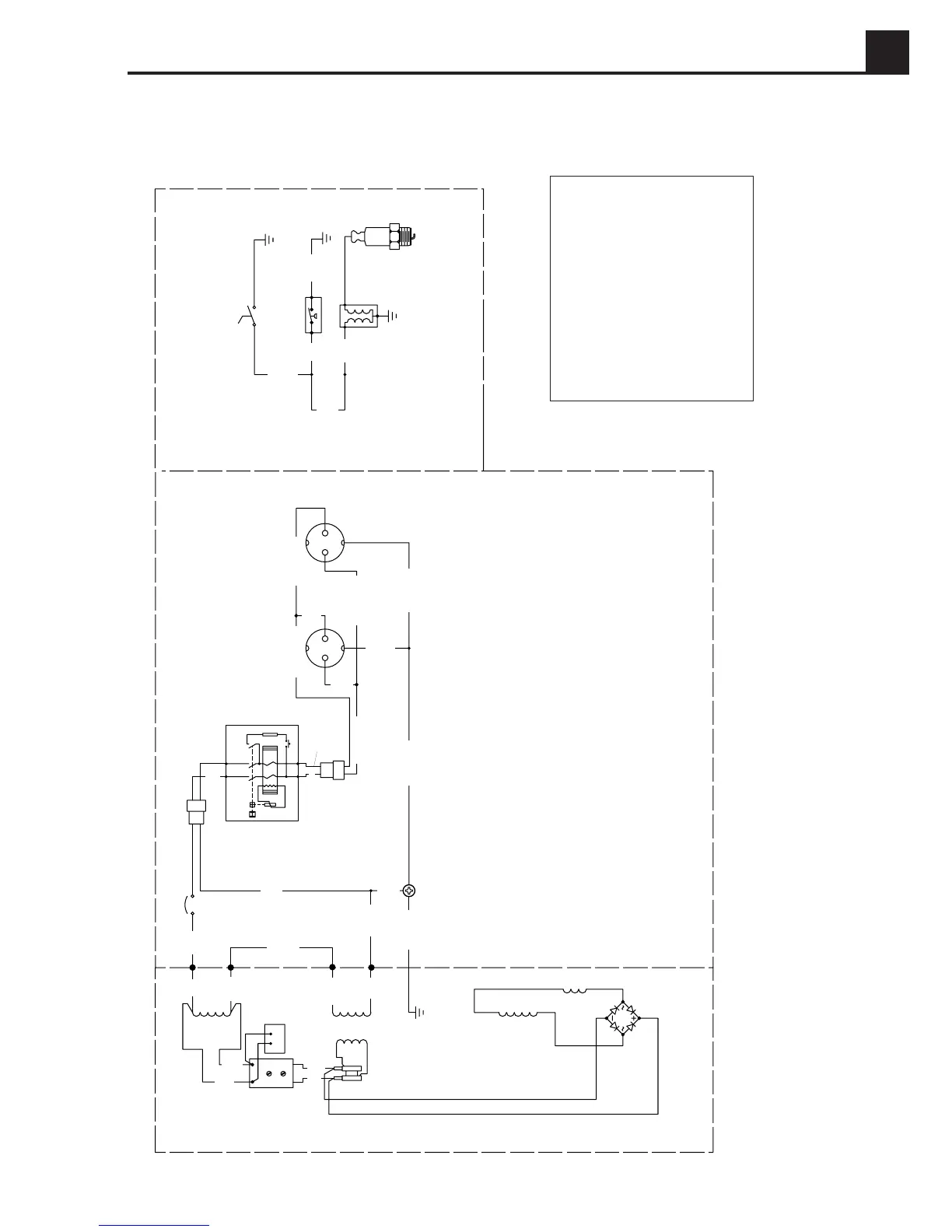
5.21 Wiring Schematics – Generator/Engine
Wiring Schematic (G3.3A Model)
1020SD83
A = Generator
B = Control box
C = Engine
1 = Main stator winding
2 = Main circuit breaker
3 = Earth-leakage circuit breaker
(G3.3AE only)
4 = 16 Amp receptacle
5 = Ignition switch
OFF
ON
1
2
T
2
4
3
1
2
F2
F1
4
Z1
Z1
Z2
Z2
R
W
LL/W
R/B
LL/B
R/B
LL/B
R/B
R/Gr
LL/B
LL/Gr
G/Y
G/Y
G/Y
L/L
L
Br
B
R
B
B
Y
B/R
G
5
C
6
4
BA
3
2
1
11
12
10
9
8
7
1
3
L1
L2
F1
F2
Z3
Z3
R/W
1
R
1
2
4
LL/W
Br
G/Y
G/Y
Wire Colors
B - Black
G - Green
L - Blue
P - Pink
R - Red
LL-Light blue
W- White
Y - Yellow
Br - Brown
Gr - Gray
Or - Orange
Pr - Purple
T - Tan
6 = Oil level switch
7 = Coil
8 = Choke
9 = Auxiliary winding
10 = Rotor winding
11 = Radio interference suppressor
12 = Automatic voltage regulator
 Loading...