5A-9
50 HZ PORTABLE GENERATORS G3.3A/G4.6A/GS4.6A/GS5.7A 5A
Restoring Residual Magnetism to the Brush Type Generators
Disconnect leads F1 and F2 from the brush holder (a). Run the generator at its normal speed and apply 12 volts from
a battery to the brush holder for approximately 3 seconds. Ensure the positive lead is applied to the brush holder nearest
the bearing housing. The output voltage of the generator, with the 12 volt supply connected, should be approximately
normal voltage. See Figure 5-12.
Stop the generator and reconnect leads F1 – F2.
CAUTION: Ensure the battery leads are connected to the brush holder with the correct polarity, and leads F1 – F2
are isolated from each other and earth. Loss of residual magnetism will result if leads touch ground, each other, or wrong
polarity.
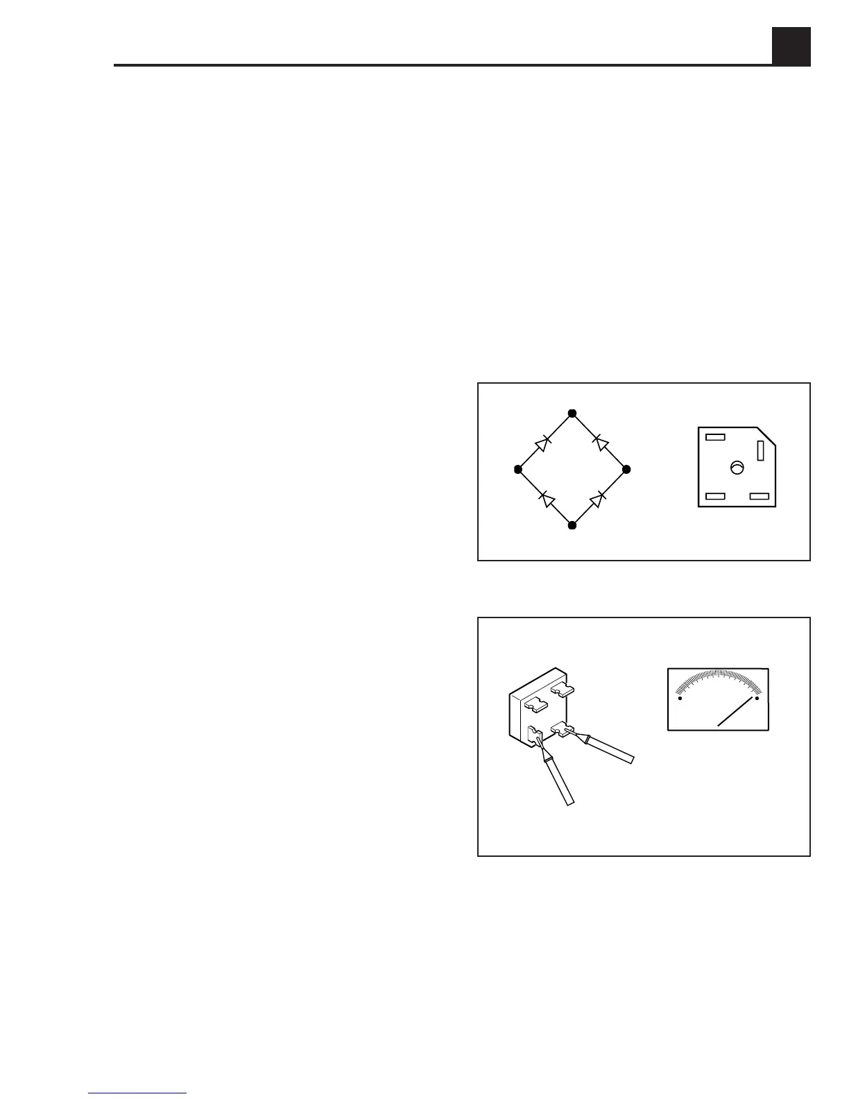
5.12 Testing the Bridge Rectifier
Accessing the Bridge Rectifier
1. Remove the generator cover.
2. Remove leads Z2 and Z3 from the bridge rectifier (b),
and leads F1 and F2 that go to the brush assembly.
Checking Bridge Rectifier
To check the rectifier, follow these steps:
1. Set multi-meter on R x 1000 range.
2. Remove all wires connected to the rectifier.
3. Place the meter probes on two adjacent rectifier
terminals and check resistance value. See Figure
5-13.
4. Reverse the probes and recheck.
5. The meter should indicate low resistance in one
direction and a high resistance in the other direction.
6. Repeat this procedure for each adjacent set of termi-
nals on the rectifier until all four diodes have been
checked.
Figure 5-12. Diode Bridge
Z2
F2
Z3
F1
F2
F1
Z3
Z2
1023SD52
Figure 5-13. Checking Diode Bridge
1023SD98
5.13 Testing the Choke
To test the choke remove wires Z1 and Z3 from the
choke (c) and the choke assembly. The resistance
value of the choke should be 7.5 ohms.
 Loading...