,,
/NLVNRWHLSSL
Markku
/VWULSHWDSH
date
author
inspected and approved
name
material
Arkki A3
finishing
Description
author & date
24.10.07
SDJH
5HYLVLRQ
7LWOH )LQQLVKQDPH
(QJOLVKQDPH 4XDQWLW\
'25) 7HLSSLPPP7(6$),;
$/.XOPD[[ /[[DOXPLQLXP
442 mm (17
13
/
32
”)
295 mm (11
5
/
8
”)
XC Duo
431 mm (16
31
/
32
”)
309 mm (12
5
/
32
”)
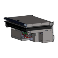
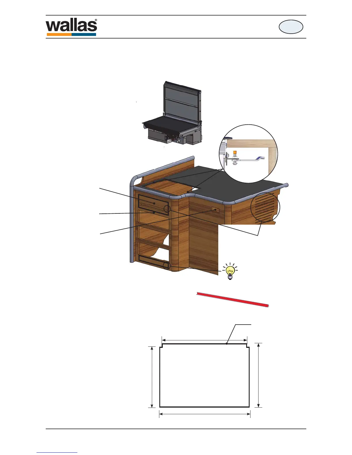
Installation
en
Stove installation
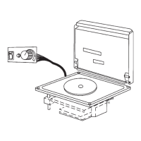
Saw a cut-out (see picture) for the stove and the control panel in your chosen loca-
tion.
The length of the control panel cable is 3 m.
2
Ensure that there is
suI¿Fient sSaFe unGer
the stove for cables and
hoses.
3
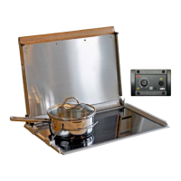
The control panel
should be installed on
a vertical surface.
Note! The unit
dissipates heat to its sur-
roundings, and the control
panel thermostat and Sun
Switch. will not operate
as planned if installed too
close to the unit.
Select the location for the
control panel to suit the
intended use.
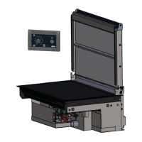
You can also fabricate a
detachable panel to go in
front of the stove. This will
facilitate installation and
maintenance.
Measurements of the stove installation cut-out.
5
Glue the L-shape pro-
¿le to the edge of hole.
1
The stove requires a replacement
air opening of at least 100 cm
2
.
Ensure that the air circulation under the
stove is suf¿cient.
When the replacement air open-
ing is at Àoor level, the heat will
be better transferred to the Àoor
level.
Please pay atten-
tion to all numbered
items!
4
Ensure that there is suf¿cient space
between the stove and the vertical
surface to facilitate installing and detach-
ing the device.
D10361B
- 45 -
XC Duo
490541G
 Loading...