3 Functional Description Thermo 90
302
3.4 Switch-off
When switching the heater off, the operation indicator
on the timer/switch extinguishes. Com
bustion ends and
run-down is initiated. Circulation pump and combustion air
fan, however, continue operation to cool down the heater
(run-down) and are automatically deactivated after about
90 seconds. A reactivation of the heater during run-down
is permitted.
Room temperature control by me
ans of the vehicle's own
heating blower may be provided in addition to employing
a room thermostat.
3.5 Functions of the Heater in TRS
Vehicles
The heater is started using the switch. A TRS condition
(forced deactivation) will be released after
– the vehicle engine is turned off
– a conveyor facility is started
with the short run-down termi
nating after 20 seconds.
Then the control unit is in the "error lockout" mode. Prior
t
o reactivation the On/Off switch must be set to "Off".
The isolation switch (emergency off switch) must only be
ope
rated in case of emergency, as the heater is switched
off without run-down (overheating possible).
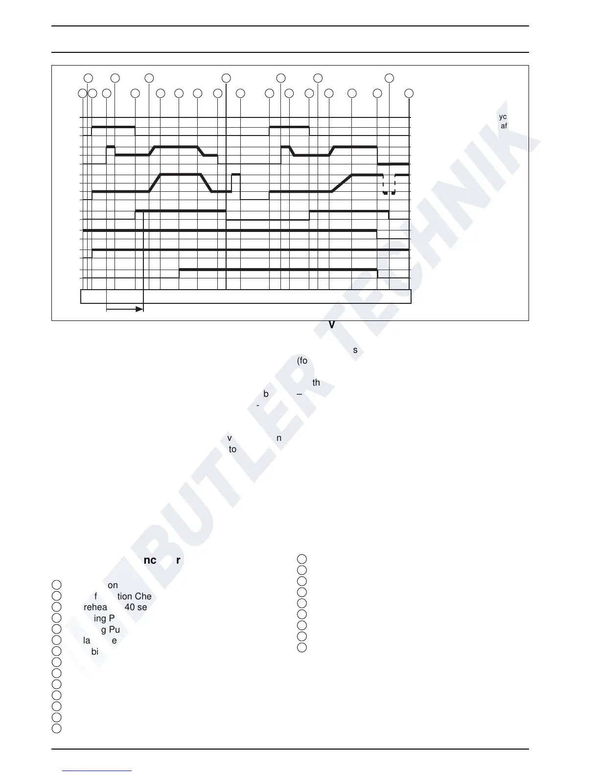
Fig. 301 Functional Sequence
Functional Sequence for Thermo 90
Switch-on
Configuration Check
Preheating 40 sec. (cycled)
Dosing Pump Priming 5 - 7 sec. (1)
Dosing Pump / Part Load (1/4)
Flame Sensor Take-over
Stabilisation Time
Full Load
Vehicle Blower »On«
Control Range
Control Idle
Flame Sensor »cold« (0)
Run-down completed
Preheating 15 – 20 sec. (cycled)
Dosing Pump Priming 5 – 7 sec. (1)
Dosing Pump / Part Load (1/4)
Flame Sensor Take-over
Stabilisation Time
Coolant Temperature down
Full Load
Switch-off (run-down)
Flame Sensor "cold" (0)
Run-down completed
A Glow Plug
B Dosing Pump
C Com
bustion Air Fan
D F
lame Sensor
E Oper
ation Indicator Light
F Circulation Pump
A
B
C
D
E
F
G
1
0
1
0
0
0
0
0
0
1
1
1
1
1
1
/4
1
/2
1
/4
*
30 80 90 75 70 °C
2
 Loading...