Thermo 90 9 Repair
909
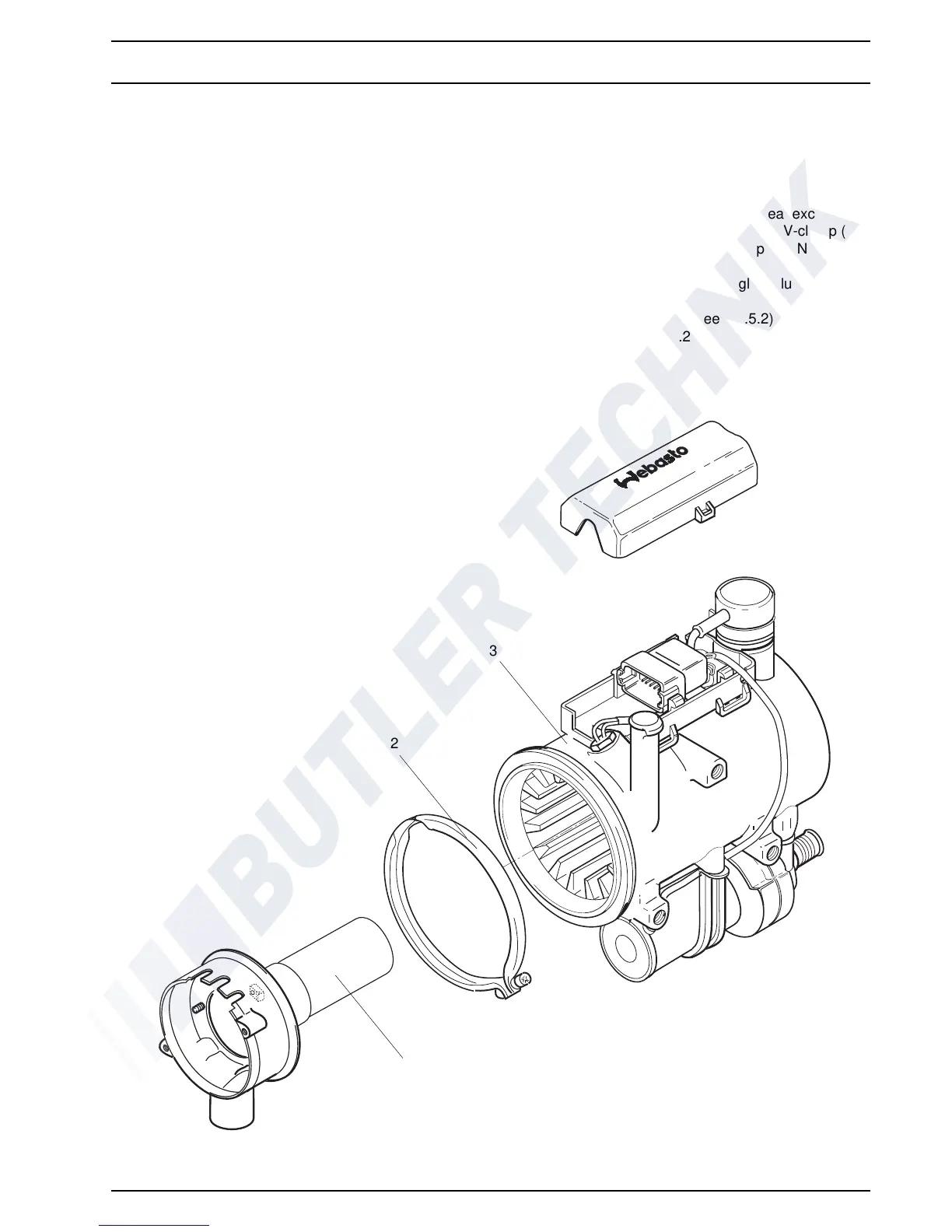
9.2.7 Replacement of Burner Head
9.2.7.1 Removal
1. Remove heater (see 8.7.1.1).
2. Remove combustion air
fan (see 9.2.5.1).
3. Remove burner, flame sensor, and glow plug
(see 9.2.6.1).
4. Remove attachment screw of V-clamp (2, Fig. 906)
and
pull off clamp.
5. Withdraw burner head (1) from heat exchanger (3)
a
nd remove.
6. Perform procedures on components after
disasse
mbly (see 9.1.1).
9.2.7.2 Installation
NOTE
Burner head and exhaust outlet pipe
can still be aligned
during installation in vehicle.
1. Insert burner head (1, Fig. 906) into heat exchanger
(
3), align as necessary and secure with V-clamp (2).
2. Torque attachment screw of V-clamp to 3 Nm ± 10%
as re
quired.
3. Install burner, flame sensor, and glow plug
(se
e 9.2.6.2).
4. Install combustion air fan (see 9.2.5.2).
5. Install heater (see 8.7.1.2).
Fig. 906 Replacement of Burner Head
Thermo 90
1 Burner Head
2V-Clamp
3 Heat Exchanger
1
2
3
NOTE
One of the newer models Thermo 90 shown. Older
models have the cable of the temperature limiter located
on the side.
Illustration is also applicable for heater Thermo 90 S.
 Loading...