Thermo 90 7 Circuit Diagrams
701
7 Circuit Diagrams
7.1 General
The circuit diagrams (Figs. 702 and 703) show possible
circuits of the heater Thermo 90 with
– 3-times-clock
– TRS equipment
The circuit diagrams (Figs. 704 through 706) show
po
ssible circuits of the heater Thermo 90 S with
– standard timer
– TRS equipment
– TRS equipment without aux
iliary drive
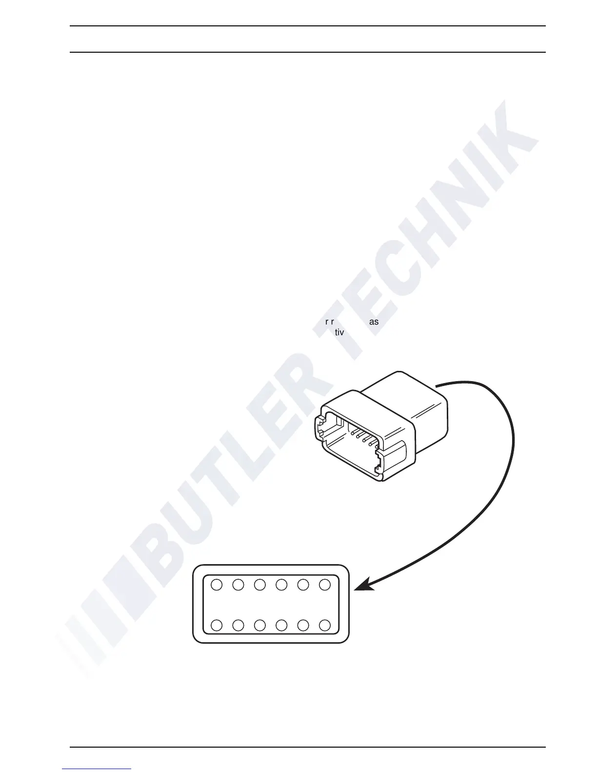
Fig. 701 shows the pin assignment (X1) for Thermo 90
an
d Thermo 90 S.
CAUTION
The –poles must not be looped or reversed as some
co
mponents are controlled by negative polarity.
Fig. 701 Pin Assignment
789101112
654321
1 = Glow Plug +
2 = Temperature Limiter +
3 = Flame Sensor +
4 = Temperature Sensor +
5 = Circulation Pump +
6 = Combustion Air Fan +
7 = Combustion Air Fan –
8 = Circulation Pump –
9 = Temperature Sensor –
10 = Flame Sensor –
11 = Temperature Limiter –
12 = Glow Plug –
View from rear
 Loading...