9 Repair Thermo 90
906
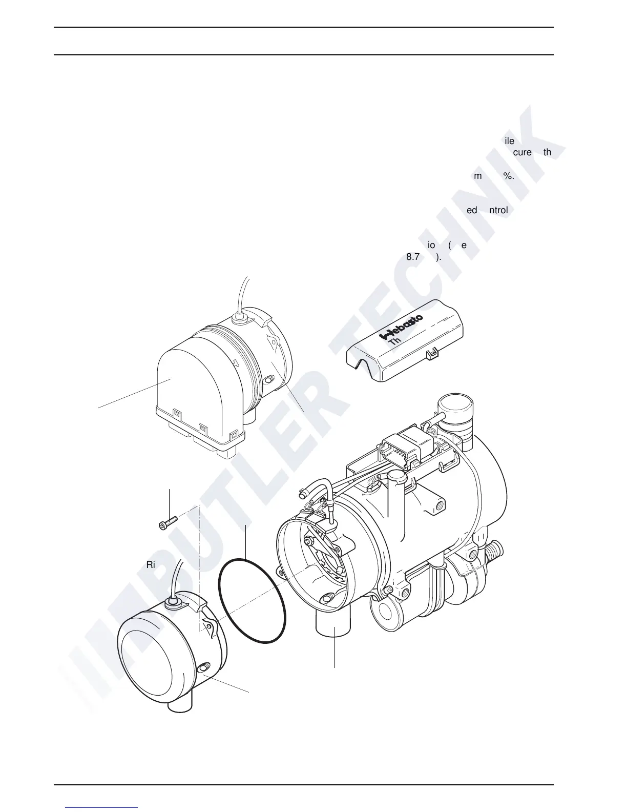
9.2.5 Replacement of Combustion Air Fan
9.2.5.1 Removal
1. Remove heater (see 8.7.1.1).
2. Disconnect electrical conne
ctions (see 9.2.1.1).
3. Remove screws (2, Fig. 904).
4. Pull combustion air fan (1) from burner head (4) and
r
emove together with profiled packing ring (3).
NOTE
On heater Thermo 90 S with flanged control unit
r
emove control unit as required.
5. Perform procedures on components after
dis
assembly (see 9.1.1).
9.2.5.2 Installation
NOTE
Locate packing ring (3, Fig. 904) properly; do not
sq
ueeze.
1. Bring combustion air fan (1) with new profiled
pack
ing ring (3) in assembly position and secure with
screw
s (2).
2. Torque tighten screws (2) with 3 Nm ± 10%.
NOTE
On heater Thermo 90 S with flanged control unit install
control unit as
required.
3. Make electrical connection
s (see 9.2.1.2).
4. Install heater (see 8.7.1.2).
Fig. 904 Replacement of Combustion Air Fan
Thermo 90
Thermo 90 S
Control Unit
1
2
3
4
1
NOTE
One of the newer models Thermo 90 shown.
Older models have the cable of the
temperature limiter located on the side.
1 Combustion Air Fan
2 Screw (2)
3 Profiled Packing Ring
4 Burner Head
 Loading...