9 Repair Thermo 90
902
9.2 Disassembly and Assembly
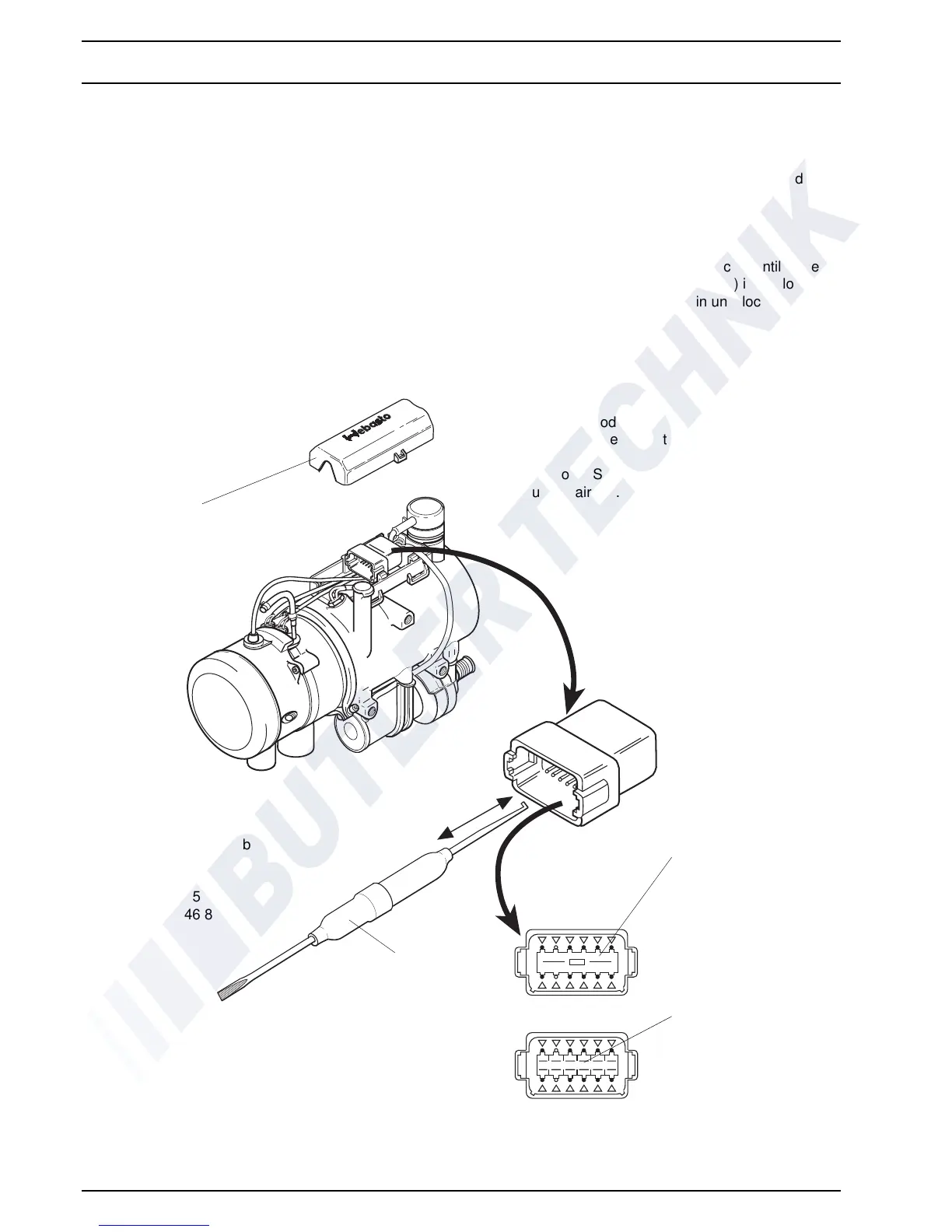
9.2.1 Electrical Connections (Fig. 901)
9.2.1.1 Disconnecting Electrical Connections
(Connection X1)
NOTE
All electrical connections are joined in the connector.
Prior to removal of a component, the relevant electrical
c
onnections first have to be disconnected.
On heater Thermo 90 S with flanged combustion air fan
co
nnector X1 on heater and connection X12 on control
unit must be disconnected and reconnected after making
electrical connections.
1. Remove top cover from heater.
2. Using removal tool (hook end) withdraw lock
wedge
from connector.
3. Using removal tool (screw driver end) press down
r
elevant locking tab and keeping tab depressed
withdraw cables from connector.
9.2.1.2 Making Electr
ical Connections
1. Slide cable into relevant contact pocket until locked.
2. Using removal tool (screw driver end) insert lock
we
dge in connector and press in until locked.
3. Fit top cover.
Fig. 901 Electrical Connections
Thermo 90
Lock Wedge
Locking Tab
(12 off)
Top Cover
Removal Tool
Supplier of Removal Tool
(Order No. DT RT1)
Compagnie Deutsch GmbH
Fraunhoferstr. 11b
82152 Martinsried
Tel. 0 89 / 8 99 15 70
Fax 0 89 / 8 57 46 84
NOTE
One of the newer models Thermo 90 shown. Older
models have the cable of the temperature limiter located
on the side.
Heater Thermo 90 S may have the control unit located on
the combustion air fan.
 Loading...