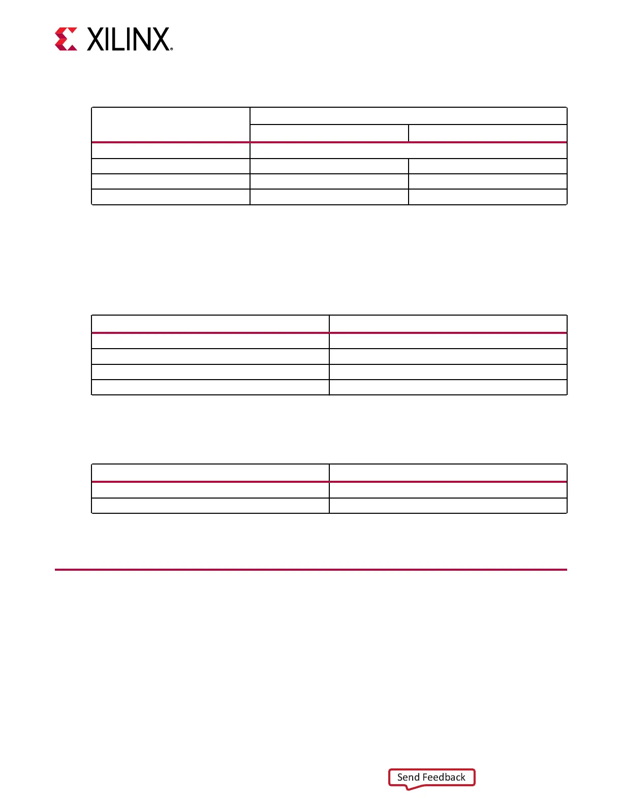
Table 4: Card Status LEDs
Reference Designator
Description
ES Production
DS1 When FPGA is configured, LED is blue, otherwise it remains Off
DS2 System healthy when green
1
Not populated
DS3 Warning or alarm when orange
1
Not populated
DS4 Power fault when red Not populated
Notes:
1. Functionality is not yet defined.
Ethernet status LEDs are located on the top-le, front panel above the SFP-DD modules. The
LED denions are given in the following tables.
Table 5: ES Ethernet Status LEDs
Reference Designator Description
SFPDD_0_ACT Dedicated to Activity and is only green
1
SFPDD_0_STA Dedicated to Link and is yellow/green
1
SFPDD_1_ACT Dedicated to Activity and is only green
1
SFPDD_1_STA Dedicated to Link and is yellow/green
1
Notes:
1. Functionality is not yet defined.
Table 6: PQ Ethernet Status LEDs
Reference Description
QSFP_0_ACT Dedicated to Activity and is only green
1
QSFP_0_STA Dedicated to Link and is yellow/green
1
Notes:
1. Functionality is not yet defined.
Card Power System
The Alveo U50 card has separate power rails for FPGA fabric and HBM memory. Developers
must ensure their designs do not draw too much power for each rail. More informaon can be
found in the Known Issues table of the Alveo U50 Data Center Accelerator Card Installaon Guide
(UG1370). To monitor, limited power system telemetry is available through the I2C IP. I2C IP is
instanated during the FPGA design process which begins aer the Alveo Data Center
accelerator card is selected from the Vivado Design Suite Boards tab. Refer to Design Flows for
more informaon.
Chapter 4: Card Component Description
UG1371 (v1.2) December 18, 2019 www.xilinx.com
Alveo U50 Accelerator Card User Guide 19
 Loading...


