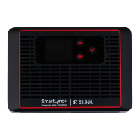
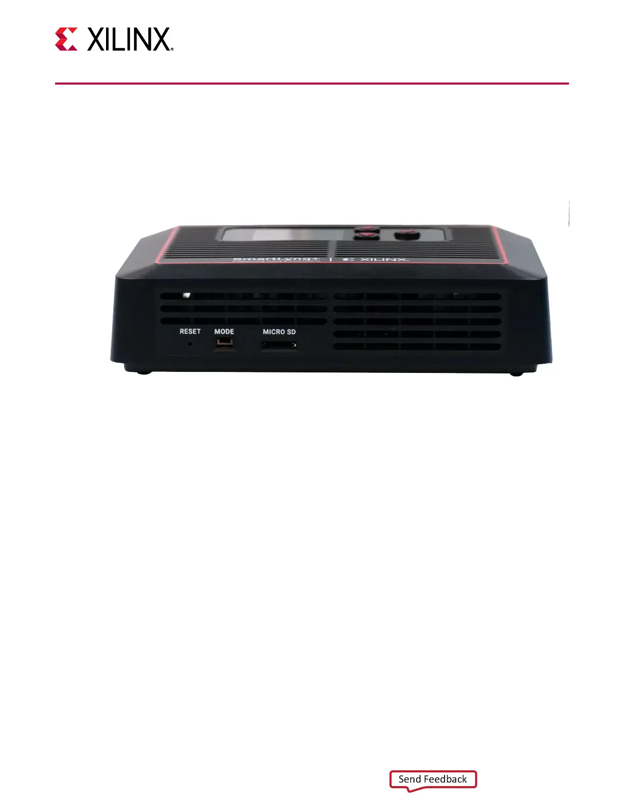
Front View
The reset pin, mode selector switch, and micro-SD card slot are located on the front of the
SmartLynq+ Module, as shown in the following gure.
Figure 5: Front View Connections
The SmartLynq+ Module MODE switch seng determines the source from which the module
boots. When the mode is set towards MICRO SD, the module boots using the SD card image.
When the MODE switch is set away from MICRO SD, the module boots from the EMMC image.
Note that you must have wrien an image to the eMMC for the system to boot properly.
Chapter 2: Connectors
UG1514 (v1.0) March 8, 2021 www.xilinx.com
SmartLynq Module+ 10
 Loading...