Home
Xilinx
Network Hardware
SmartLynq Plus
Xilinx SmartLynq Plus User Manual
4
of 1
of 1 rating
41 pages
Give review
Manual
Specs
To Next Page
To Next Page
To Previous Page
To Previous Page
Loading...
Chapter 2
C
o
n
n
e
c
t
o
r
s
Connectors on the S
martL
ynq+ Module are locat
ed as follow
s.
H
o
s
t
S
i
d
e
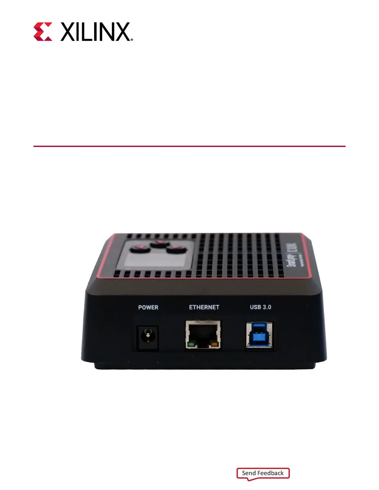
The DC pow
er
, USB 3.0, and Ethernet connectors ar
e located on the
le
side of the S
martL
ynq+
Module, as sho
wn in the following
gur
e.
Figur
e 3:
Host-Side Connections
Chapter
2:
Connectors
UG1514 (v1.0) March 8, 2021
www.xilinx.com
SmartLynq Module+
8
S
e
n
d
F
e
e
d
b
a
c
k
7
9
Table of Contents
default chapter
2
Revision History
2
Table of Contents
3
Chapter 1: Overview
5
Features
5
Description
5
Chapter 2: Connectors
8
Host Side
8
Target Side
9
Front View
10
Chapter 3: Installing the Smartlynq+ Module
11
Chapter 4: USB 3.0 Host Connection
12
Minimum Host System Requirements
12
Default USB 3.0 IP Setting
12
Windows USB 3.0 Driver Setup
13
Linux USB 3.0 Setup
16
Changing the USB 3.0 IP Setting
18
Chapter 5: Ethernet Connection
19
Changing the Ethernet IP Settings
19
Chapter 6: Smartlynq+ Module Display
20
Chapter 7: JTAG Target Interface
21
Chapter 8: GPIO Target Interface
25
Chapter 9: HSDP Target Interface
28
Chapter 10: Parallel Debug Interface
35
Appendix A: Regulatory and Compliance Information
38
4
Based on 1 rating
Ask a question
Give review
Questions and Answers:
Need help?
Do you have a question about the Xilinx SmartLynq Plus and is the answer not in the manual?
Ask a question
Xilinx SmartLynq Plus Specifications
General
Brand
Xilinx
Model
SmartLynq Plus
Category
Network Hardware
Language
English

 Loading...