Chapter 10
Parallel Debug Interface
Note: The 38-pin MICTOR interface is currently not supported. See the SmartLynq+ Module wiki page for
the latest informaon.
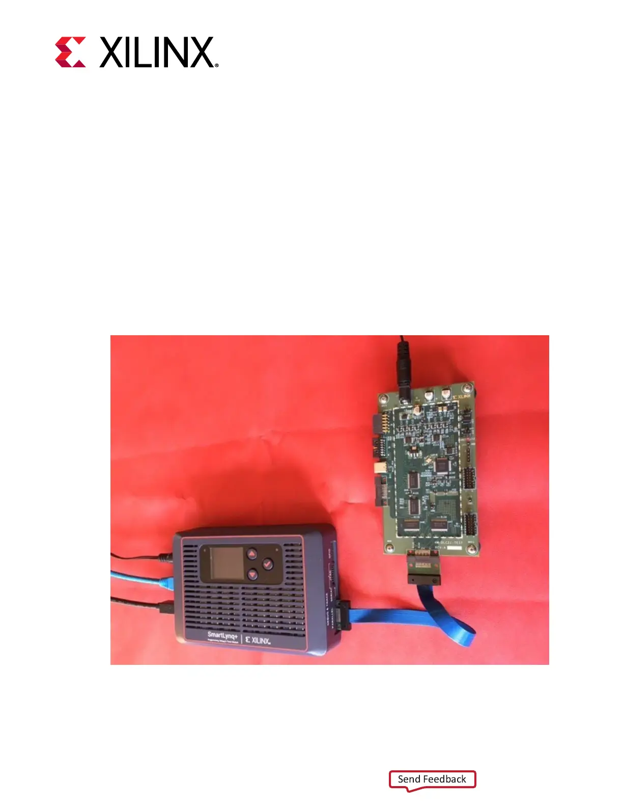
The SmartLynq+ Module provides a MICTOR interface for high-speed trace capture. The
interface supports 16-bit wide parallel trace and includes status and sync signals. The interface is
implemented with a 38-pin, 0.64 mm pitch connector (TE P/N 5767044-1). The following gure
shows the SmartLynq+ Module connected to the MICTOR interface on a target board.
Figure 16: SmartLynq+ Connected to MICTOR Interface on a Target Board
The following gure shows the MICTOR connector pinout. The signals are described in the table
that follows.
Chapter 10: Parallel Debug Interface
UG1514 (v1.0) March 8, 2021 www.xilinx.com
SmartLynq Module+ 35
 Loading...