Chapter 7
JTAG Target Interface
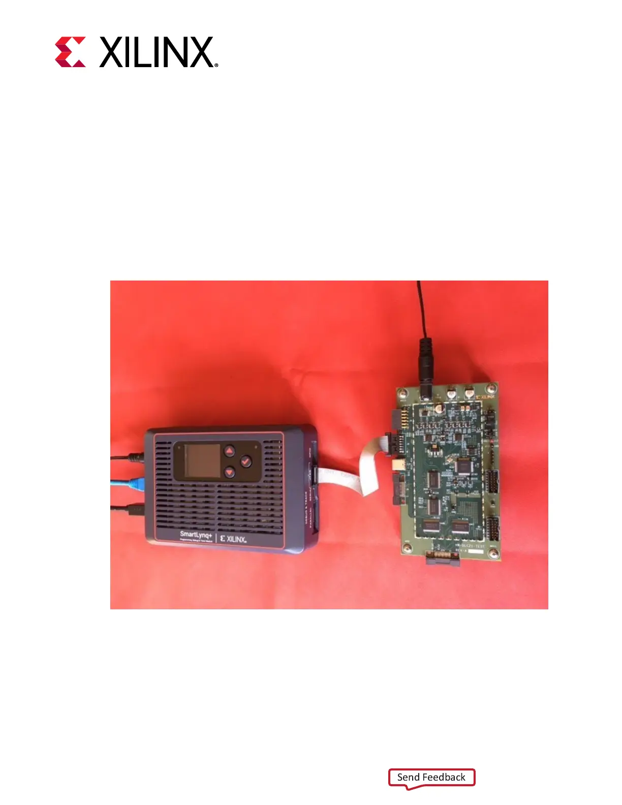
The JTAG target interface uses a standard 14-pin connector. Xilinx recommends using the
provided 6-inch ribbon cable or 6-inch ying leads to connect the SmartLynq+ Module to the
JTAG interface on the target board, as shown in the following gure.
Figure 6: SmartLynq+Module JTAG Connection to the JTAG Interface on a Target Board
To take advantage of the ribbon cable, a mang connector must be incorporated into the target
board, as is implemented on Xilinx evaluaon boards. This connector is normally installed only
during prototype development. When the producon hardware is funconal and the JTAG
devices can be congured from alternate sources, the connector can be eliminated from the
board cost. Maintaining the footprint for this connector is recommended if space permits.
Chapter 7: JTAG Target Interface
UG1514 (v1.0) March 8, 2021 www.xilinx.com
SmartLynq Module+ 21
 Loading...