Chapter 8
GPIO Target Interface
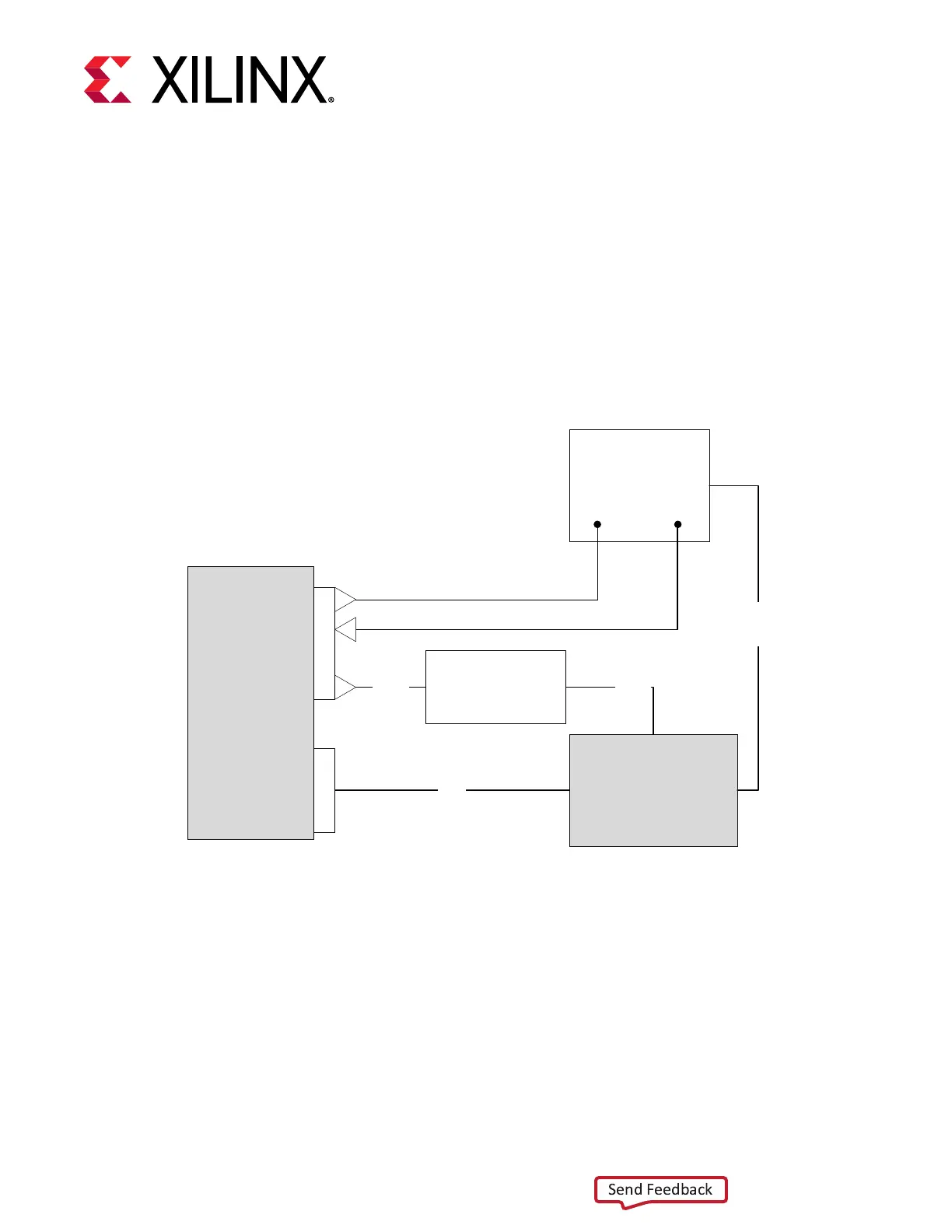
The SmartLynq+ Module GPIO can be used for a variety of basic input/output operaons on the
target board. The following gure shows a sample setup where the SmartLynq+ Module is
connected to an oscilloscope, power supply, and a target board.
Figure 9: Sample Setup: SmartLynq+ Module to an Oscilloscope
Oscilloscope
SmartLynq
Data Cable
Target Board
Target Board
Power Supply
JTAG
On/Off
Power
Target Board
Analog
Measurement
J
T
A
G
G
P
I
O
Oscilloscope Trigger In
Oscilloscope Trigger Out
X25142-022321
In this setup, the SmartLynq+ Module uses an output from the GPIO pins to drive a trigger input
to the oscilloscope. The oscilloscope drives an input to module to allow monitoring a trigger
event from the oscilloscope. With this arrangement, it is possible to take analog measurements
with the oscilloscope and synchronize trigger events with the SmartLynq+ Module. The gure
also shows how a power supply or relay could be controlled through the GPIO port so as to
power on/o the target board. Thus, through the GPIO ports, it is possible to simplify the driving
and sensing of addional instruments connected to the target system. Note that the latency of
such a trigger is unpredictable because these are soware-driven triggers.
Chapter 8: GPIO Target Interface
UG1514 (v1.0) March 8, 2021 www.xilinx.com
SmartLynq Module+ 25
 Loading...