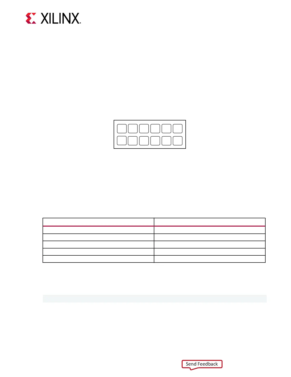
The GPIO 2x6 connector, shown in the following gure, is available for 8-bit stac read/write
operaons. The 8-bit GPIO interface does not turn on unl the GPIO_VREF pin 11 on the GPIO
2x6 interface is powered by 3.3V. You can aach ying leads to any of the standard 0.1-inch
headers listed in the following table to connect to the GPIO interface.
Figure 10: GPIO Connector
9
7 5 3 1
8 6 4 2
3.3V_OUT
GND
GPIO_7
GPIO_6
GPIO_5
GPIO_4
GPIO_VREF
NC
GPIO_3
GPIO_2
GPIO_1
GPIO_0
11
10
12
X25129-022221
Table 5: Header Manufacturers
Manufacturer Part Number
Samtec TSW-106-23-S-D
Amphenol FCI 67997-212HLF
3M 929836-01-06-RK
Hirose A1-12PA-2.54DSA(71)
Sullins PBC06DAAN
The 8-bit general purpose read/write interface is controlled by the update_hw_gpio shell
command. The GPIO interface defaults to read mode on power-on-reset. The format of this
command is as follows:
update_hw_gpio <direction> <value>
Chapter 8: GPIO Target Interface
UG1514 (v1.0) March 8, 2021 www.xilinx.com
SmartLynq Module+ 26
 Loading...