Power to the SmartLynq+ Module is supplied by a 12V / 2A DC module connected to the Power
connector. Note that when the DC module is connected to the power connector, the SmartLynq+
Module turns on. The Ethernet connector is always acve when the cable is powered. When an
ethernet cable is connected to the SmartLynq+ module, the cable inializes the ethernet port and
a host can communicate with it by using the IP address shown on the display screen. The USB
3.0 is an alternate host interface that can be used for host communicaon. The USB 3.0 interface
is also acve upon power up and inializes on connecon to an acve USB connecon.
Target Side
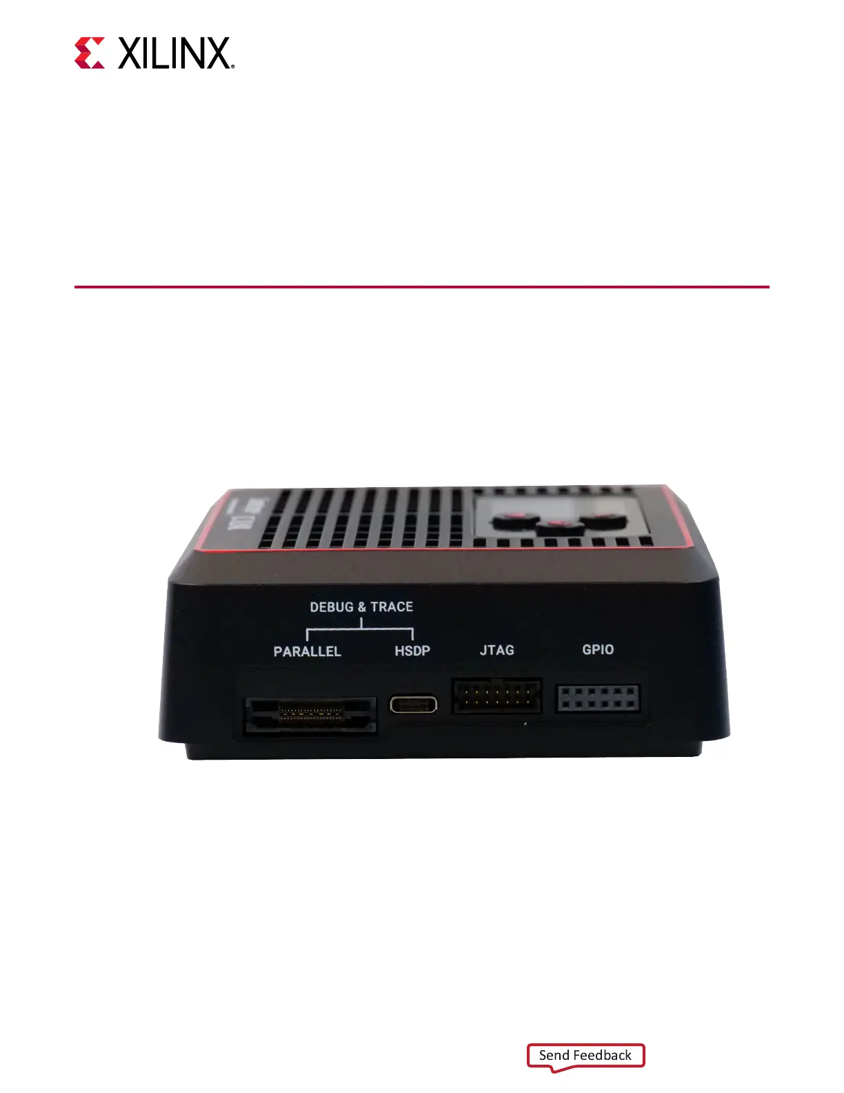
The GPIO, JTAG, HSDP, and MICTOR connectors are on the right side of the SmartLynq+
Module, as shown in the following gure.
Figure 4: Target-Side Connections
For standard HSDP communicaon use the HSDP connector. Typically, this is the only
connecon required to a target board such as the Versal ACAP VCK190 evaluaon board. For
target boards without the HSDP connector use the 14 pin JTAG connector using a ribbon cable
or ying leads. The GPIO cable provides addional low-speed signals for controlling the target or
other instruments used alongside the board under test.
Chapter 2: Connectors
UG1514 (v1.0) March 8, 2021 www.xilinx.com
SmartLynq Module+ 9
 Loading...